Air-swept efficient vertical roller mill

A vertical roller mill and air-sweeping technology, which is applied in the direction of grain processing, etc., can solve the problems of difficult adjustment of particle size, low grinding efficiency, wear of grinding mechanism, etc., and achieve small particle size range, high powder selection efficiency and high material efficiency. Effects with easy granularity

Inactive Publication Date: 2013-01-02
扬州中材机器制造有限公司
View PDF0 Cites 9 Cited by
  • Summary
  • Abstract
  • Description
  • Claims
  • Application Information

AI Technical Summary

Problems solved by technology

[0003] The current domestic vertical mills have shortcomings such as short life of the grinding mechanism, low grinding efficiency, difficulty in large-scale, poor airtightness of the feeding system, low powder selection efficiency of the powder selection system, difficult adjustment of particle size, low operating rate and difficult maintenance. Compared with foreign advanced products, the performance of vertical mills is very different, especially for the grinding of high hardness cement clinker and slag, it is difficult for domestic vertical mills to adapt
With the promotion of high-fine and high-mixing technology in recent years, blast furnace slag, which was originally used as waste, is added to cement as cement mixture after ultrafine grinding, which not only turns waste into treasure to realize comprehensive utilization of resources, but also improves the performance of cement , but the iron contained in the slag seriously wears the grinding mechanism of the mill, which affects the service life and operation rate of the mill

Method used


Image

  • Air-swept efficient vertical roller mill
  • Air-swept efficient vertical roller mill
  • Air-swept efficient vertical roller mill

Examples


Embodiment Construction

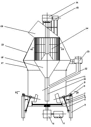
[0020] As accompanying drawing, motor one 1 drives speed reducer one 2 to run, and the grinding disc 6 that links to each other with speed reducer one 2 output shafts does rotary motion simultaneously. The material enters the collection pipe 10 from the rotary airlock feeder 13 through the feeding pipe 12 installed on the mill shell 11 and falls to the center of the grinding disc 6, and moves along the surface of the grinding disc 6 to the edge under the action of centrifugal force. A material layer is formed at the outer edge of the grinding disc 6 surface. The rotary shaft 8 and the grinding roller shaft 9 installed in the bearing seat at the upper end of the column 3 together form a rocker arm, and the hydraulic (pneumatic) spring 4 controls the large grinding roller 23 and the small grinding roller through the rocker arm composed of the rotary shaft 8 and the grinding roller shaft 9. 22 Apply grinding pressure, the grinding disc 6 drives the grinding rollers to rotate alon...


PUM


Abstract

The invention relates to the field of air-swept efficient vertical roller mill. The air-swept efficient vertical roller mill comprises a mill body; a powder selecting mechanism comprising a stator and a rotor is arranged on the upper part of the mill body; the powder selecting mechanism is connected with a discharge port; the side of the mill body is provided with a feeding pipe at the lower part of the powder selecting mechanism; the lower part of the mill body is provided with a discharge pipe corresponding to the powder selecting mechanism; the lower part of the discharge pipe is provided with a roller mechanism corresponding to the feeding pipe; and the roller mechanism is provided with a blowing device, which is a wind ring arranged on the lateral part of the roller mechanism. The wind ring arranged in the present invention enables the materials entering the feeding tube to be blown upward; and then vortex flow is formed through disturbance on the airflow by the rotor; solid particles with large granularity gather into the center of the airflow and fall down continuously; at the same time, the air bumps against an inner wall of the powder selecting mechanism shell and a guide vane to settle down the solid particles with large granularity. Therefore, the present invention has advantages of high powder selecting efficiency, easily adjustable the particle granularity and small granularity range.

Description

technical field [0001] The invention relates to the field of an air-swept high-efficiency vertical roller mill. Background technique [0002] The vertical roller mill integrates the functions of grinding, drying, classification (powder selection) and conveying, and has the advantages of high efficiency, low energy consumption, low abrasion, high operation rate, compact structure, small site and space occupation, low noise, The fineness of the product is easy to adjust and other obvious advantages, and it is more and more widely used in the grinding and ultrafine grinding of cement (raw meal, coal, clinker), metallurgical slag, materials, chemical industry and other materials. [0003] The current domestic vertical mills have disadvantages such as short service life of the grinding mechanism, low grinding efficiency, difficulty in large-scale, poor airtightness of the feeding system, low powder selection efficiency of the powder selection system, difficult adjustment of parti...

Claims


Application Information

Patent Timeline
IPC IPC(8): B02C15/04
Inventor 杨生强
Owner 扬州中材机器制造有限公司
Why Eureka
Try Eureka