Facing head feeding mechanism and facing head

A technology of feed mechanism and flat rotating disk, which is applied in the direction of metal processing machinery parts, metal processing equipment, manufacturing tools, etc., and can solve the problems of poor transmission rigidity in the feed direction, stroke limitation, limited cutting accuracy and speed of flat rotating disk, etc. , to achieve the effect of improving transmission rigidity, compact transmission structure and increasing processing efficiency

Inactive Publication Date: 2013-01-02
SANY GRP
View PDF6 Cites 1 Cited by
  • Summary
  • Abstract
  • Description
  • Claims
  • Application Information

AI Technical Summary

Problems solved by technology

[0002] At present, in the field of mechanical processing, more and more irregular parts with large holes are processed, so the CNC flat rotary disc structure is used more and more on the spindle of the boring and milling machining center machine tool, but the boring and milling machine currently used is flat There are certain technical problems in each of the turntables: (1) In the case of a flat turntable slide plate, the cutting accuracy and speed of the turntable are limited, and a counterweight device must be added; (2) When the turntable is working, the feed The rigidity of the direction transmission is poor; (3) The structure of the horizontal rotary disc with multi-radial feed slides is complicated, and it occupies a large volume of the headstock; big limit

Method used


Image

  • Facing head feeding mechanism and facing head
  • Facing head feeding mechanism and facing head
  • Facing head feeding mechanism and facing head

Examples


Embodiment 1

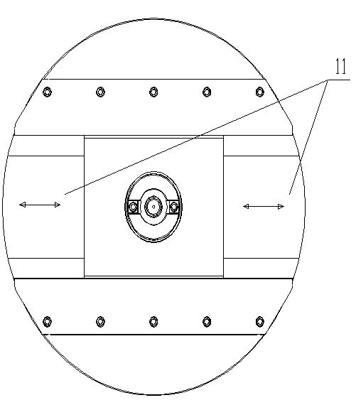
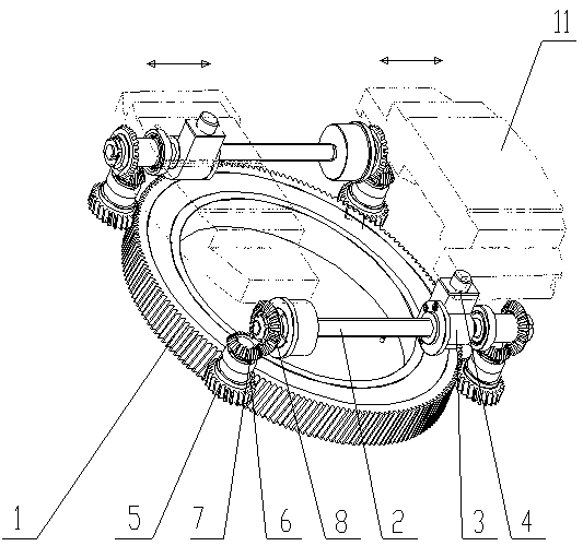
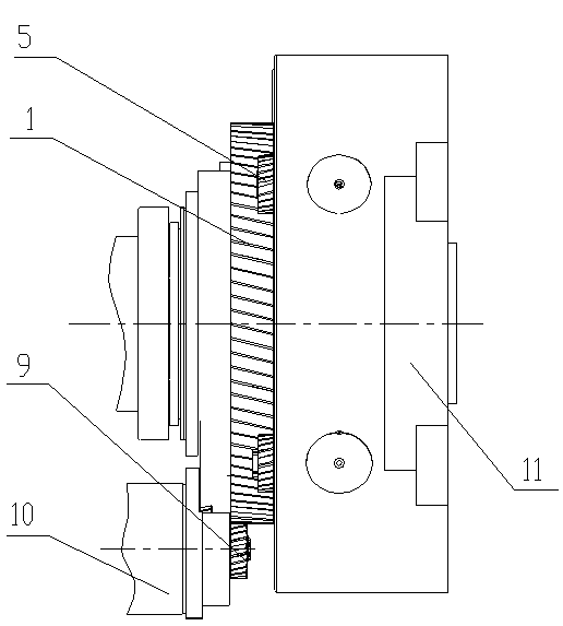
[0023] Such as figure 1 , figure 2 and image 3 Shown is an embodiment of a feed mechanism of the present invention, comprising a large gear 1, a transmission mechanism, a lead screw 2, a lead screw nut 3 and a transmission block 4, two lead screws 2, two lead screws 2 They are parallel to each other and symmetrical about the axis of the large gear 1. There are four sets of transmission mechanisms. The two ends of each lead screw 2 are respectively connected to the large gear 1 through a set of transmission mechanisms. The pair of bars, transmission block 4 is connected and fixed with leading screw nut 3.

[0024] The working principle of the above technical solution is: the power is transmitted to the lead screw 2 through the transmission mechanism through the rotation of the large gear 1, and the rotation of the lead screw pair drives the movement of the lead screw nut 3 and the transmission block 4 installed on the lead screw 2 , in order to realize the movement process...

Embodiment 2

[0031] Such as figure 1 , figure 2 and image 3 As shown, the embodiment of the present invention differs from Embodiment 1 in that the transmission of the second bevel gear 8 can be replaced by a worm gear pair, the transmission block 4 can be made into one part with the lead screw nut 3 or the slide plate 11, and the rest are the same. The same parts are not repeated here.

[0032] In the embodiment of the present invention, by manufacturing the transmission block 4 and the lead screw nut 3 or the slide plate 11 into one component, the installation is quicker and the production efficiency is improved. The structure of the double slides 11 has a compact transmission structure, which can also achieve a larger feed stroke for a flat rotating disk with a smaller diameter; one sliding plate is driven by two small gears, which improves the transmission rigidity of the flat rotating disk.

[0033] Embodiments of the present invention also include a flat-rotating disk, which inc...


PUM


Abstract

The invention discloses a facing head feeding mechanism and a facing head, which relate to the field of feeding mechanisms for machine tools. The facing head feeding mechanism is characterized by comprising a large gear, four groups of transmission mechanisms, two lead screws, lead screw nuts and transmission blocks, wherein the two lead screws are parallel to each other and are symmetrical with each other relative to the axis of the large gear; the two ends of each lead screw are respectively connected with the large gear through one group of transmission mechanisms; the lead screw nuts are sleeved on the lead screws to form a lead screw pair; and the transmission blocks and the lead screw nuts are fixedly connected with one another. The facing head feeding mechanism has the beneficial effects that the facing head is provided with dual sliding plates, so that the machining efficiency is doubled; according to symmetrical transmission structures, the dynamic balance requirement on the facing head can be met, and a counter weight of the facing head is eliminated; each sliding plate is driven by two pinions, and thus the transmission rigidity of the facing head is improved; and the dual sliding plate structure can realize high feeding travel of the small-diameter facing head.

Description

technical field [0001] The invention relates to a feeding structure of a machine tool, in particular to a feeding mechanism of a flat rotating disk and a flat rotating disk. Background technique [0002] At present, in the field of mechanical processing, more and more irregular parts with large holes are processed, so the CNC flat rotary disc structure is used more and more on the spindle of the boring and milling machining center machine tool, but the boring and milling machine currently used is flat There are certain technical problems in each of the turntables: (1) In the case of a flat turntable slide plate, the cutting accuracy and speed of the turntable are limited, and a counterweight device must be added; (2) When the turntable is working, the feed The rigidity of the direction transmission is poor; (3) The structure of the horizontal rotary disc with multi-radial feed slides is complicated, and it occupies a large volume of the headstock; big limit. Contents of t...

Claims


Application Information

Patent Timeline
Patent Type & Authority Applications(China)
IPC IPC(8): B23Q1/30B23Q5/40
Inventor 赵云云孟祥东李小龙郭春亮
Owner SANY GRP
Why Eureka
Try Eureka