
Core drilling drill with barrier crushing and chip-discharge functions

A core drill bit and drill bit technology, which is applied in the aerospace field, can solve problems such as cutting tool wear, drill pipe bending deformation, and drill sticking, and achieve the effects of solving frictional heating, reducing frictional heating, and reducing frictional heating

Inactive Publication Date: 2013-01-02
HARBIN INST OF TECH
View PDF4 Cites 9 Cited by
  • Summary
  • Abstract
  • Description
  • Claims
  • Application Information

AI Technical Summary

Problems solved by technology

Due to the influence of the vacuum environment of the moon, the low thermal conductivity of the lunar soil and the inability to use cutting fluid to cool the drilling tool during the drilling process, the heat generated by the friction between the drill bit and the lunar soil cannot be dissipated during the drilling process, which will affect the breakage of the drilling tool. Footage efficiency and coring quality; and the structure of the lunar regolith is complex, the density of the lunar regolith cannot be determined with depth, the distribution of rocks in the surface layer of the regolith is random, and the interlaced particles of the lunar regolith have high mechanical strength, which will lead to severe wear of cutting tools during drilling , fracture or falling off, drill pipe bending and deformation to cause drill sticking and other phenomena; and a coring mechanism must be installed inside the drill bit, so the existing core drilling tool structure must be redesigned to meet its special requirements

Method used


Image

  • Core drilling drill with barrier crushing and chip-discharge functions

Examples


Embodiment Construction

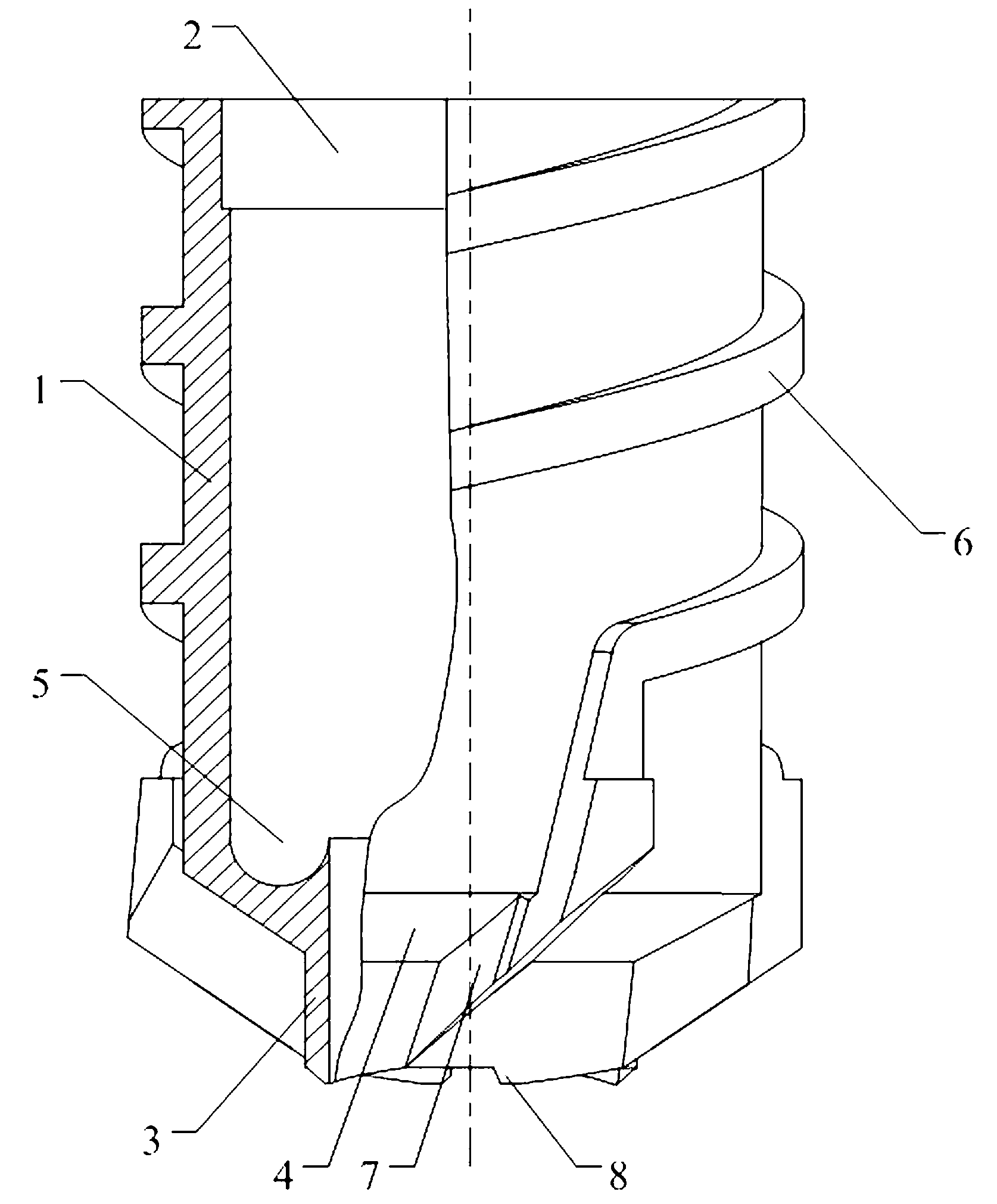
[0016] Examples of the present invention figure 1 As shown, the drilling core bit with the function of breaking barrier and chip removal is provided with a hollow cylindrical drill base 1, the upper end of which is provided with a drill pipe connecting portion 2 for connecting with the drill pipe, and the lower end is radially retracted to form a The isolating cutting ring 3, the convex table surface formed by the retraction of the drill base 1 is a slope 4, and a coring mechanism placement space 5 is formed between the drill base 1 and the isolating cutting ring 3, which is used to place a tubular coring mechanism; the drill base 1 The outer surface is connected with an outer spiral 6, and the outer surface of the isolation cutting ring 3 and the inclined surface 4 are connected with cutting tools 7 uniformly distributed in the circumferential direction. flush; the lower end of the isolation cutting ring 3 is provided with circumferentially distributed annular cutting teeth 8...


PUM


Abstract

The invention relates to a core drilling drill with barrier crushing and chip-discharge functions. The core drilling drill is characterized by comprising a drill matrix which is in a hollow cylinder shape. A drill stem connection portion is arranged at the upper end, the lower end is radially retracted inwards to form a separation cutting ring, a boss surface formed by the inwards-retracted drill matrix is an inclined surface, and a coring mechanism arranging place is formed between the interior of the drill matrix and the separation cutting ring; and outer spirals are connected onto the outer surface of the drill matrix, and cutting tools evenly distributed on the circumference are connected onto the outer surface and the inclined surface of the separation cutting ring. According to the core drilling drill with barrier crushing and chip-discharge functions, space nearby the cutting tools is large, so that reduction of frictional heating between the drill and lunar soil is facilitated; besides, the surface of the drill is hardened and smoothed, so that the frictional heating is reduced greatly; and crushing, separation and chip discharging effects during the drilling are good, and the structure can further solve frictional heating problem to a certain extent, so that the drill is applicable to drill and sample on lunar surfaces.

Description

technical field [0001] The invention belongs to the field of aerospace, and relates to a drilling tool for drilling soil on the surface of the moon in the aerospace environment, in particular to a drilling core bit with the functions of breaking, blocking and chip removal. Background technique [0002] Aerospace is a frontier project for human beings to explore the natural world. Going into space has become an indispensable symbol of a scientific and technological power. The lunar exploration project is a relay stage of my country's aerospace industry. The results will provide valuable experience for the next step of outer space exploration. The lunar exploration project is mainly to reveal the mystery of the lunar environment through telemetry and remote sensing and the final moon landing. After the moon landing, a series of scientific research projects will be carried out on the moon. Each The links are very important, one of which is to obtain samples of lunar surface mater...

Claims


Application Information

Patent Timeline
IPC IPC(8): E21B10/00
Inventor 唐德威姜生元全齐全邓宗全田野王清川王扬张宏志
Owner HARBIN INST OF TECH
Learn More