Engine transient air-intake control system and control method

A technology of control system and control method, which is applied in the direction of engine control, combustion engine, machine/engine, etc. It can solve the problems that the engine power output cannot achieve good results, the air-fuel ratio cannot be effectively controlled, and the air-fuel ratio is out of balance. , to achieve the effect of improving the precise control of air-fuel ratio, meeting the transient intake demand, and improving the combustion process

Active Publication Date: 2013-01-02
姜添棋
View PDF7 Cites 2 Cited by
  • Summary
  • Abstract
  • Description
  • Claims
  • Application Information

AI Technical Summary

Problems solved by technology

Whether it is an ordinary naturally aspirated engine, a turbocharged engine, or an engine with a variable intake system, the intake system is a passive intake mode. Under different speed conditions, the air must pass through a certain length of intake pipe. Inflate air to each cylinder, resulting in pulsation of air quality under different speed conditions. The engine inhales intermittent fluctuating air flow during actual operation, and the air-fuel ratio is out of balance, resulting in poor engine power output. , while the exhaust gas emitted by the engine is not standard
Especially when the vehicle is in a transient state, the vehicle engine’s demand for air intake is constantly changing, and the air-fuel ratio cannot be effectively controlled. At present, there is no equipment that can accurately control the amount of air intake required by the vehicle in a transient state. Cause the air-fuel ratio of the vehicle to be too high or too low during transient operation, which will reduce the performance of the vehicle, or cause the fuel to not be fully combusted

Method used


Image

  • Engine transient air-intake control system and control method
  • Engine transient air-intake control system and control method
  • Engine transient air-intake control system and control method

Examples


Embodiment Construction

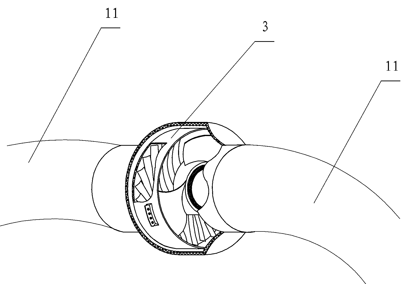
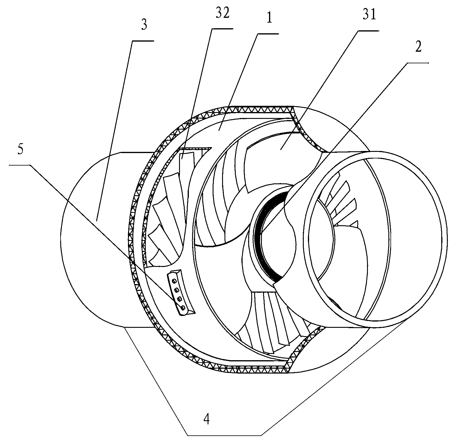
[0038] The engine transient air intake control system involved in the present invention consists of figure 1 As shown, it includes a blower 3 arranged on the intake pipe 11 between the engine intake and the intake manifold to change the air flow direction, and a control system for receiving vehicle status information and controlling the operation of the fan according to the vehicle status information. The fan 3 can be a fan of NMB (Minebéa) company, the model is 3630FTD4WB66E51. In order to describe its structure more clearly, a schematic structural diagram of the fan 3 is provided in this embodiment. Its main structure is as follows figure 2 As shown, a fan housing 1 is included, and a fan motor 2 is arranged in the fan housing 1. The terminal 5 of the fan motor 2 is arranged on the fan housing 1, and the front end of the fan motor 2 is provided with a fan blade that rotates after being powered on. 31, the rear end of the fan motor 2 is provided with a static fan blade 32; a...


PUM


Abstract

The invention discloses an engine transient air-intake control system. The engine transient intake control system comprises a fan (3) and a control device, wherein the fan (3) is arranged above an air-intake pipeline (11) between an air inlet and an air-intake manifold and is used for adjusting the air flow strength of intake air and converting the air flow into vortex; and the control device is used for acquiring the state information of a vehicle and controlling the running speed of the fan (3) based on the state information of the vehicle. The invention also discloses a method for controlling such engine transient air-intake control system. The method comprises the steps of acquiring and processing the running state information of the vehicle through the control system, and sending out a command to control and adjust the rotating speed of the fan based on the current running state of the vehicle. With the adoption of the method provided by the invention, the air intake speed of an engine is increased, the vortex strength in a cylinder is improved, and the effect of mixing the oil and gas is improved; on the other hand, the air quality in the air-intake pipeline is regulated, the air supply of the engine under different working conditions is controlled, and the air-fuel ratio of the engine under different working conditions is precisely controlled, therefore, the combustion process is improved; and moreover, the fuel consumption and the exhaust emission are reduced while improving the power of the engine.

Description

technical field [0001] The invention belongs to the field of engine air intake control, and in particular relates to an engine transient air intake control system. At the same time, the invention also provides a control method based on the engine transient air intake control system. Background technique [0002] At present, during the operation of any kind of engine, the air intake state of the intake pipeline is in a passive intake state, and the amount of intake air depends entirely on the intake efficiency of the engine when it is running or is forced to obtain by consuming the energy of the engine itself. Whether it is an ordinary naturally aspirated engine, a turbocharged engine, or an engine with a variable intake system, the intake system is a passive intake mode. Under different speed conditions, the air must pass through a certain length of intake pipe. Inflate air to each cylinder, resulting in pulsation of air quality under different speed conditions. The engine i...

Claims


Application Information

Patent Timeline
Patent Type & Authority Applications(China)
IPC IPC(8): F02B33/40F02B31/06F02D23/00F04D27/00
CPCY02T10/146Y02T10/144Y02T10/12
Inventor 姜新民尹万建
Owner 姜添棋
Why Eureka
Try Eureka