Piston channel engine

An engine and piston technology, applied in the field of piston engines, can solve the problems of large flow resistance, large impact of clearance volume, and high consumption of throttling loss, so as to reduce flow resistance and throttling loss, be easy to implement, and increase displacement Effect

Inactive Publication Date: 2013-01-02
ZEROQ SCI & TECH
View PDF5 Cites 0 Cited by
  • Summary
  • Abstract
  • Description
  • Claims
  • Application Information

AI Technical Summary

Problems solved by technology

[0003] The invention discloses a piston channel engine, which solves the problems of the existing engine, such as small degree of freedom in setting air distribution channels, large flow resistance, large throttling loss consumption, large impact on clearance volume, and high requirements on the pressure bearing capacity of the whole machine.

Method used


Image

  • Piston channel engine
  • Piston channel engine
  • Piston channel engine

Examples


Embodiment 1

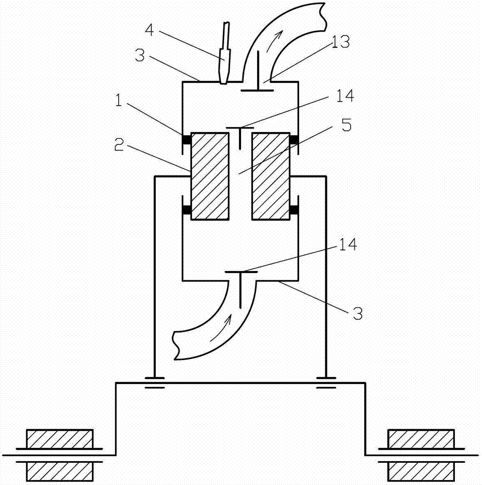
[0031] Such as figure 1 The shown piston channel engine comprises a cylinder 1 and a laterally connected piston 2, the cylinder 1 is matched with the laterally connected piston 2, and a cylinder head 3 is provided at both ends of the cylinder 1, and the cylinder head 3 A cylinder head valve is provided on the cylinder head, and the cylinder head valve includes an intake valve 14 and an exhaust valve 13 respectively arranged on the two cylinder heads 3, and the cylinder head 3 provided with the exhaust valve 13 A fuel inlet 4 is provided on the side connecting piston 2, and a channel 5 communicating with its two ends is provided on the side connecting piston 2, and a piston valve valve is provided on the channel 5, wherein the piston valve valve is set as an intake valve 14; Said lateral connection piston 2 is rotatably connected with the connecting rod journal of the crankshaft through the connecting rod.

[0032] The piston tunnel engine described in this embodiment can wor...

Embodiment 2

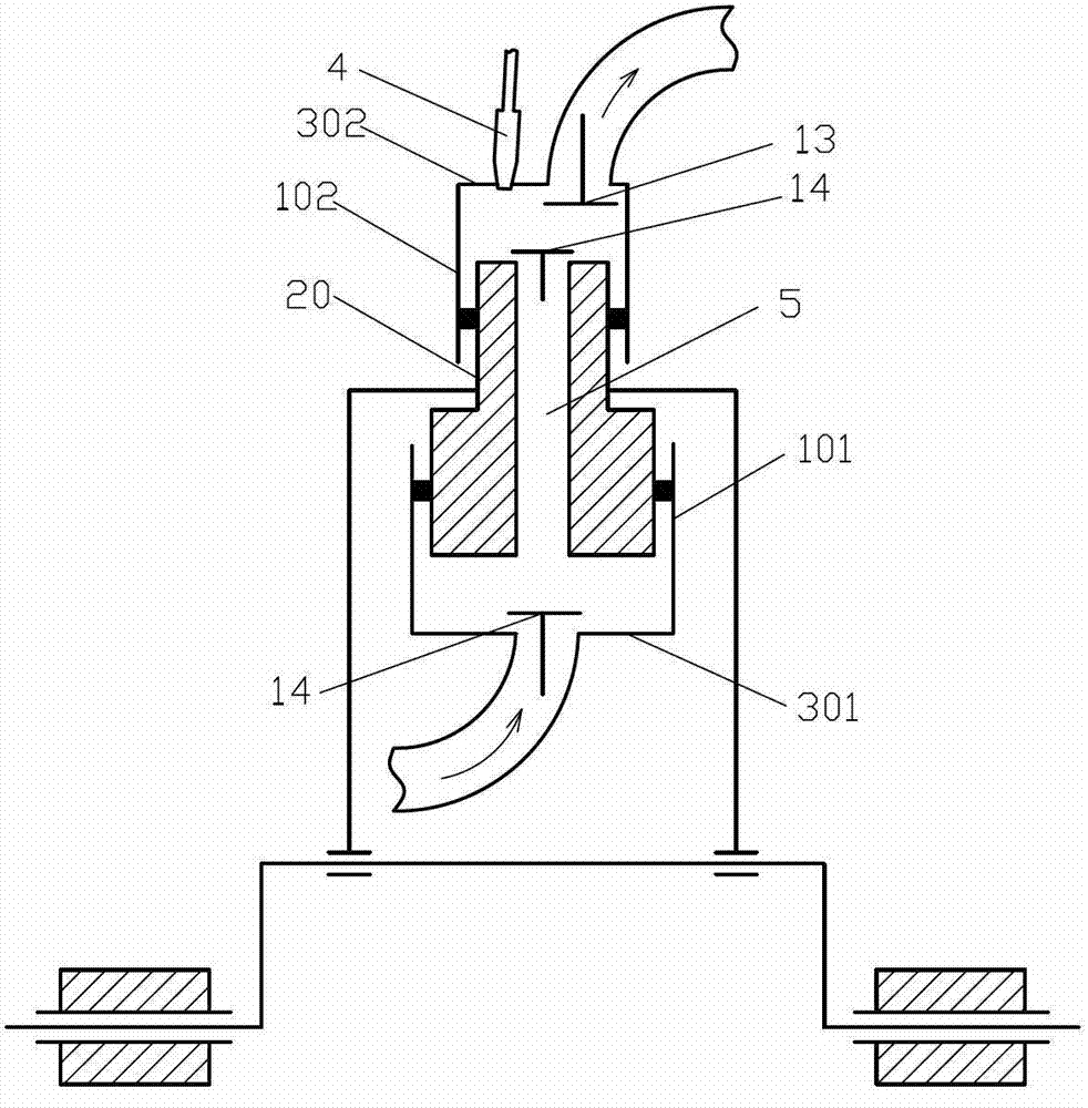
[0035] Such as figure 2 The shown piston tunnel engine comprises a large-diameter cylinder 101, a small-diameter cylinder 102 and a double-diameter laterally connected piston 20, the large-diameter cylinder 101 is matched with the large-diameter section of the dual-diameter laterally connected piston 20, and the The small-diameter cylinder 102 cooperates with the small-diameter section of the double-diameter side connecting piston 20, and a large-diameter cylinder head 301 is arranged at the end of the large-diameter cylinder 101, and a small-diameter cylinder head 302 is established at the end of the small-diameter cylinder 102, A cylinder head distribution valve is set on the large-diameter cylinder head 301, a cylinder head distribution valve and a fuel inlet 4 are set on the small-diameter cylinder head 302, and a passage connecting the two ends of the double-diameter lateral connecting piston 20 is provided. 5. The passage 5 is provided with a piston valve, wherein the c...

Embodiment 3

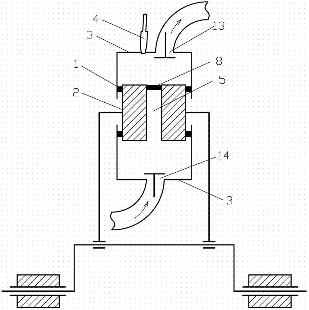
[0039] Such as image 3The difference between the shown piston channel engine and Embodiment 1 is that the piston valve is set as a check valve 8, and the flow direction of the check valve 8 is provided by the cylinder provided with the intake valve 14. One end of the cover 3 flows to one end of the cylinder head 3 where the exhaust valve 13 and the fuel inlet 4 are provided.


PUM


Abstract

The invention discloses a piston channel engine which comprises a cylinder and a side direction connection piston. The cylinder is matched with the side direction connection piston, a cylinder cover is arranged at two ends of the cylinder, a cylinder cover air distribution door is arranged on the cylinder cover, a fuel inlet is arranged on at least one cylinder cover, a channel for communicating two ends of the side direction connection piston is arranged on the side direction connection piston, and a piston air distribution door is arranged on the channel. An air valve is arranged on a piston of the piston channel engine so that quantity of valves arranged on the cylinder or the cylinder cover is reduced, circulation resistance and throttling loss are further reduced, efficiency of the engine is improved, simultaneously degree of freedom of arrangement of air distribution channels is increased, and the piston channel engine has a wide application prospect.

Description

technical field [0001] The invention relates to the field of engines, in particular to a piston engine. Background technique [0002] Due to the nature of the intermittent operation of the piston engine, the flow resistance and throttling loss of the valve valve in the cylinder head are important factors affecting the efficiency and power per liter of the piston engine. Due to the limited spatial position of the piston engine cylinder head, and the structure of setting the cylinder head valve or valve seat port on the cylinder liner often causes the increase of the piston engine pollution emission. Therefore, need to invent the engine of a kind of novel valve structure. Contents of the invention [0003] The invention discloses a piston channel engine, which solves the problems of the existing engine such as small degree of freedom in air distribution channel setting, large flow resistance, large throttling loss consumption, large influence of clearance volume, and high r...

Claims


Application Information

Patent Timeline
Patent Type & Authority Applications(China)
IPC IPC(8): F02B75/40F02F1/24F02F3/00
Inventor 靳北彪
Owner ZEROQ SCI & TECH
Why Eureka
Try Eureka