Water hammer-resistant constant-pressure pressure reducing valve
A pressure reducing valve and water hammer technology, applied in the field of pressure reducing valves, can solve problems such as damage to pressure reducing valve equipment, no anti-water hammer device, complex structure, etc., and achieve the effects of avoiding strong impact, low cost, and small size
- Summary
- Abstract
- Description
- Claims
- Application Information
AI Technical Summary
Problems solved by technology
Method used
Image
Examples
Embodiment 1
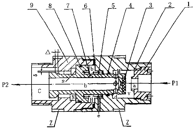
[0032] Such as figure 1 The shown anti-water hammer constant pressure reducing valve, the present invention consists of a valve seat sleeve 1, a valve body 2, a valve disc 3, a seal 4, a spring 5, a gasket 6, a valve core 7, a grid ring 8 and The valve body is composed of 9 parts.
[0033] The valve body 2 is a stepped cylinder with a stepped inner hole. The valve seat cover 1 is screwed into the water inlet at the upstream end, and a stop is provided to ensure that the inner hole a of the valve seat cover 1 is consistent with the center line of the water inlet , The downstream end of the valve seat sleeve 1 is provided with an annular edge as the valve seat of the valve port V; the cavity between the valve body 1-2 and the valve seat sleeve 1 is the intermediate cavity M; the water inlet of the valve body 1-2 is used outside The thread is connected with the water supply pipe.
[0034] The inner holes on the upstream side and the middle section of the valve body two 9 are cylinder...
Embodiment 2
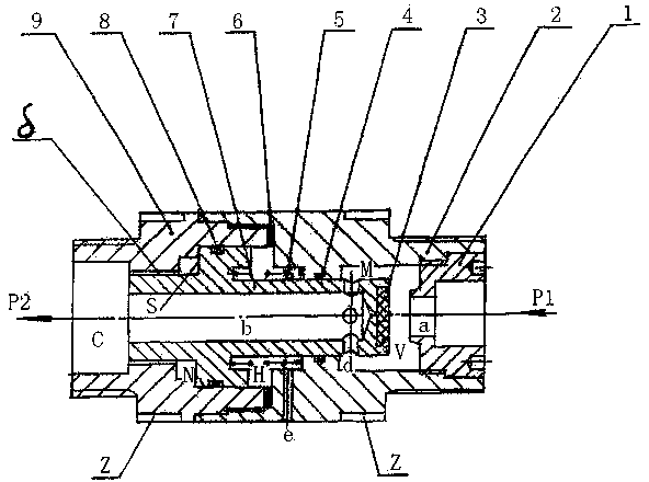
[0040] figure 2 As shown, the matching gap between the outer diameter of the sleeve on the downstream side of the valve core 7 and the inner diameter of the middle section of the valve body 9 is δ. When a shock wave is generated, this gap acts as a damping agent to prevent the valve core 7 from rapidly moving upstream.
Embodiment 3
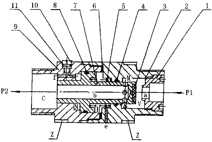
[0042] image 3 As shown, the outer diameter of the sleeve on the downstream side of the valve core 7 and the cylinder barrel in the middle section of the valve body 9 are in a sliding fit, with a small fit clearance. A small hole f is drilled on the partition wall of the cylinder. When an impact occurs, the moving speed of the valve core 7 is controlled and adjusted by the opening of the needle valve 9.
PUM
 Abstract
Description
Claims
Application Information
 - R&D
- Intellectual Property
- Life Sciences
- Materials
- Tech Scout
- Unparalleled Data Quality
- Higher Quality Content
- 60% Fewer Hallucinations
Browse by: Latest US Patents, China's latest patents, Technical Efficacy Thesaurus, Application Domain, Technology Topic, Popular Technical Reports.
© 2025 PatSnap. All rights reserved.Legal|Privacy policy|Modern Slavery Act Transparency Statement|Sitemap|About US| Contact US: help@patsnap.com


