Zero adjustment device for rotary encoders and application method thereof

A rotary encoder and zero-position adjustment technology, which is applied in the direction of operation through the zero-adjustment method, can solve the problems of difficulty in controlling the accuracy, the encoder shaft stops at the zero position, etc., and achieves the effect of compact structure, stable transmission and convenient disassembly.

Active Publication Date: 2013-01-02
常州迈特运控电机有限公司
View PDF4 Cites 10 Cited by
  • Summary
  • Abstract
  • Description
  • Claims
  • Application Information

AI Technical Summary

Problems solved by technology

[0004] Since the rotary encoder may stop at any position in the circumferential direction during installation, usually in order to make the rotary encoder stop at the zero position, it is generally necessary to disconnect the encoder shaft from the mechanism shaft (the encoder shaft can rotate, while the mechanism shaft do not move), manually rotate the encoder shaft until the zero signal is output, since the hollow shaft of the rotary encoder needs to be fixedly connected with the shaft of the automatic control mechanism under test at the same time, it is difficult to control its accuracy
That is: the traditional manual adjustment method is difficult to stop the encoder shaft at zero quickly, accurately and reliably

Method used


Image

  • Zero adjustment device for rotary encoders and application method thereof
  • Zero adjustment device for rotary encoders and application method thereof
  • Zero adjustment device for rotary encoders and application method thereof

Examples


Embodiment 1

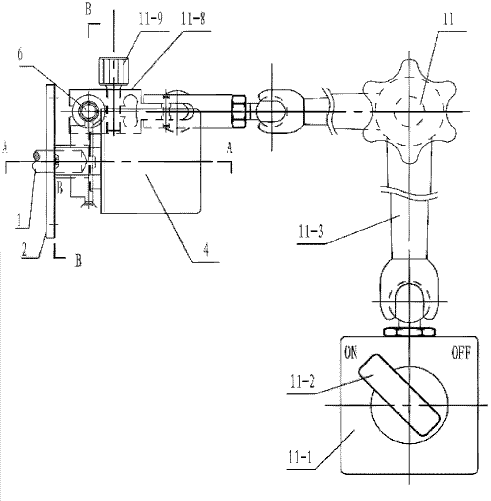
[0035] The installation method of the rotary encoder on the automatic control mechanism: the hollow rotating shaft 4-1 of the rotary encoder is connected to the rotating shaft 1 of the automatic control mechanism under test; the housing 4-3 of the rotary encoder 4 passes through an elastic bracket 4 -2 is arranged on the mounting plate 2 of the automatic control mechanism under test.

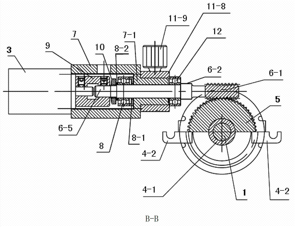
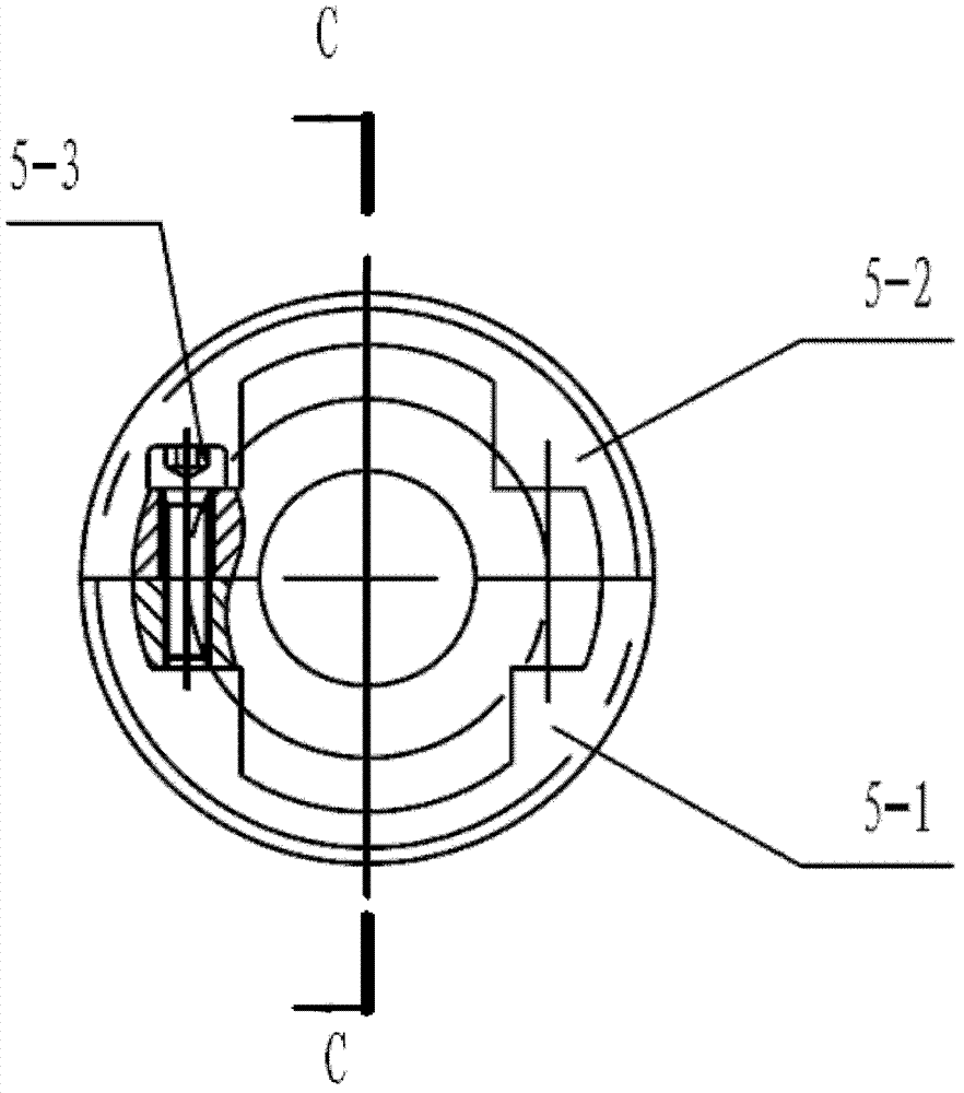
[0036] Such as Figure 1-5 The zero adjustment device of the rotary encoder comprises: an encoder acquisition card for connecting the signal output end of the rotary encoder 4 of an automatic control mechanism, a computer connected to the encoder acquisition card, an electronic handwheel, and the electronic handwheel The stepper motor driver connected to the signal output end of the wheel, the stepper motor connected to the stepper motor driver, the helical gear 5, the cylindrical worm 6 and the universal magnetic gauge base assembly 11. The stepper motor driver is adapted to drive the stepper ...

Embodiment 2

[0048] The method for using the zero position adjustment device of the rotary encoder in the above-mentioned embodiment 1 includes:

[0049] First determine the approximate position of the zero point of the rotary encoder. The signal output end of the rotary encoder is connected with the encoder acquisition card, and the encoder acquisition card is inserted into the expansion slot of the computer; the user holds the encoder housing with one hand, and slowly rotates the hollow shaft of the rotary encoder with the other hand, and the computer real-time Read the output of the rotary encoder through the encoder acquisition card and display it. At this time, the software is set to read the zero signal and display it at the zero position and stop reading the zero signal. When the user observes the computer display after the zero position Stop rotating the hollow shaft of the rotary encoder. Due to the lag of human reaction, the rotary encoder generally cannot stop exactly at the zer...


PUM


Abstract

The invention relates to a zero adjustment device for rotary encoders and an application method thereof. The device comprises an encoder acquisition card, a computer, an electronic hand wheel, a stepping motor driver, a stepping motor, a cylindrical worm, a helical gear and a universal magnetic gauge stand assembly, wherein the encoder acquisition card is used for connecting the signal output end of a rotary encoder of an automatic control mechanism, the computer is connected with the encoder acquisition card, the stepping motor driver is connected with output signals of the electronic hand wheel, and the stepping motor is connected with the stepper motor driver. In the process of operating, through rotating the electronic hand wheel, the stepping motor rotates and drives the helical gear to rotate through driving the cylindrical worm so as to drive a hollow rotating shaft, and meanwhile, the computer reads the output of the rotary encoder through the encoder acquisition card and displays whether the rotary encoder reaches a zero position; and when the rotary encoder reaches the zero position, a user stops rotating the electronic hand wheel, and the stepping motor stops rotating.

Description

technical field [0001] The invention relates to the field of mechanical automation control, in particular to a zero position adjustment device of a rotary encoder of an automatic control mechanism and a use method thereof. Background technique [0002] Generally, an automatic control mechanism with a rotating shaft needs to use a rotary encoder to detect the angle of the rotating shaft during use. When the angle of the rotating shaft is a special value (usually zero position), a part of the automatic control mechanism moves to a special position, that is, the mechanism When moving to this position, the rotary encoder rotating coaxially with the rotating shaft just outputs a zero position signal; the installation method of the rotary encoder on the automatic control mechanism: the hollow rotating shaft of the rotary encoder is driven by the rotating shaft of the automatic control mechanism under test. connected; the housing of the rotary encoder is set on the mounting plate o...

Claims


Application Information

Patent Timeline
Patent Type & Authority Applications(China)
IPC IPC(8): G01D3/06
Inventor 丁仕燕俞庆杨小斌金祥曙
Owner 常州迈特运控电机有限公司
Why Eureka
Try Eureka