
Pneumatic low-pressure sensor

A low-pressure sensor, pneumatic technology, applied in the direction of elastic deformation meter type fluid pressure measurement, etc., can solve the problems of increased operating costs for users, low sensitivity of pneumatic pressure sensors, and easy to produce misoperations, etc., to improve sensitivity, avoid misoperation, Reliable performance

Inactive Publication Date: 2013-01-02
NANYANG ZHENGTONG ELECTRICAL
View PDF4 Cites 0 Cited by
  • Summary
  • Abstract
  • Description
  • Claims
  • Application Information

AI Technical Summary

Problems solved by technology

[0002] According to the requirements of Article 7.10 of the standard GB3836.5-2004 "Electrical Equipment for Explosive Gas Atmospheres Part 5: Positive Pressure Enclosure Type "P"", the positive pressure enclosure type electrical equipment is in the positive pressure enclosure and its pipeline that may leak, The minimum positive pressure that each part should maintain relative to the external pressure: 50Pa for Px or Py type, 25Pa for Pz type; Adjust the intake pressure so that the pressure in the shell is always higher than the external pressure. Automatic adjustment of the intake pressure requires the use of a pressure sensor. The current positive pressure ventilation system or the use of electronic sensors, due to the influence of electromagnetic fields, are prone to malfunction, or use The sensitivity of the pneumatic pressure sensor is low, and the setting value of the sensor needs to be adjusted above 2000Pa, which increases the operating cost of the user

Method used


Image

  • Pneumatic low-pressure sensor
  • Pneumatic low-pressure sensor

Examples


Embodiment Construction

[0011] The present invention will be further described below in conjunction with the drawings and embodiments.

[0012] The embodiment of the pneumatic low-pressure sensor of the present invention includes:

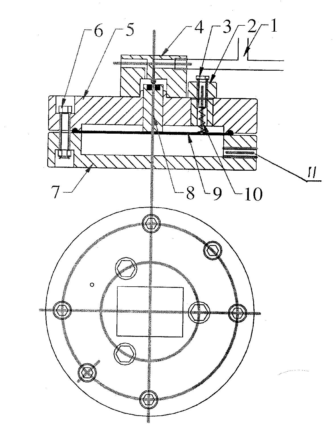
[0013] in figure 1 In the middle, the air inlet of the lower box (7) is connected with the positive pressure shell electrical equipment through the air pipe, and the housing pressure signal is input. The upper box (5) and the diaphragm (9) are connected by 4 connecting bolts (6). , The adjusting bolt (3) adjusts the elastic force of the adjusting spring (10) through the adjusting spring seat (2), the plug (8) is between the diaphragm (9) and the output connecting block (4), and the output tee (1) The output coupling block (4) is connected with the box body. When the input housing pressure signal of the lower box body (7) is greater than the elastic force of the adjusting spring (10), the diaphragm (9) presses the plug (8) to block the output connection block (4) The output po...


PUM


Abstract

The invention relates to a pressure sensor, and discloses a pneumatic low-pressure sensor. The pneumatic low-pressure sensor is mainly characterized in that the output end of the sensor adopts a three-way connection tube; a diaphragm and a plurality of adjustment springs are used for pressure setting; one outlet of the three-way connection tube is plugged via a plug head; pressure adjustment is performed by means of pure pneumatic signal feedback; the output end of the sensor is controlled by the pressure of a gas which is possible to leak in a shell; displacement for the shell is increased or reduced via a pressure adjustment valve connected with the shell, and then the pressure in the shell is always controlled to fluctuate in the range of plus / minus 5% of the set values (ranging from 100 Pa to 2000 Pa) of the sensor.

Description

Technical field [0001] The invention belongs to a pressure sensor and relates to a pneumatic low pressure sensor. Background technique [0002] According to the requirements of Article 7.10 of the standard GB3836.5-2004 "Electrical Equipment for Explosive Gas Atmosphere Part 5: Positive Pressure Enclosure Type "P"", the positive pressure enclosure type electrical equipment in the positive pressure enclosure and its pipeline that may cause leakage, The lowest positive pressure that each part should maintain relative to the external pressure: 50Pa for Px or Py type, 25Pa for Pz type; therefore, a positive pressure ventilation control system must be used for positive pressure enclosure type electrical equipment during operation. Adjust the intake pressure so that the pressure in the shell is always higher than the external pressure. Automatically adjust the intake pressure requires the use of a pressure sensor. The current positive pressure ventilation system or the electronic senso...

Claims


Application Information

Patent Timeline
IPC IPC(8): G01L7/10G01L7/12
Inventor 杜君宇王军黄荣杰郭红新王国强
Owner NANYANG ZHENGTONG ELECTRICAL
Learn More