
Measuring apparatus for continuous spectrum bidirectional scattering distribution function

A bidirectional scattering and distribution function technology, applied in the direction of color/spectral characteristic measurement, etc., can solve the problems of low measurement speed, small measurement angle, narrow measurement spectrum, etc., and achieve the effect of convenient operation, improved speed and accuracy, and simple structure

Inactive Publication Date: 2013-01-02
HARBIN INST OF TECH
View PDF1 Cites 13 Cited by
  • Summary
  • Abstract
  • Description
  • Claims
  • Application Information

AI Technical Summary

Problems solved by technology

[0024] The present invention aims to solve the problems that the continuous spectrum BSDF cannot be measured, the measurement spectrum is narrow, the measurement angle is small, and the measurement speed is low, and a fast and high-precision measurement device for the continuous spectrum bidirectional scattering distribution function is proposed.

Method used


Image

  • Measuring apparatus for continuous spectrum bidirectional scattering distribution function
  • Measuring apparatus for continuous spectrum bidirectional scattering distribution function
  • Measuring apparatus for continuous spectrum bidirectional scattering distribution function

Examples


specific Embodiment approach 1

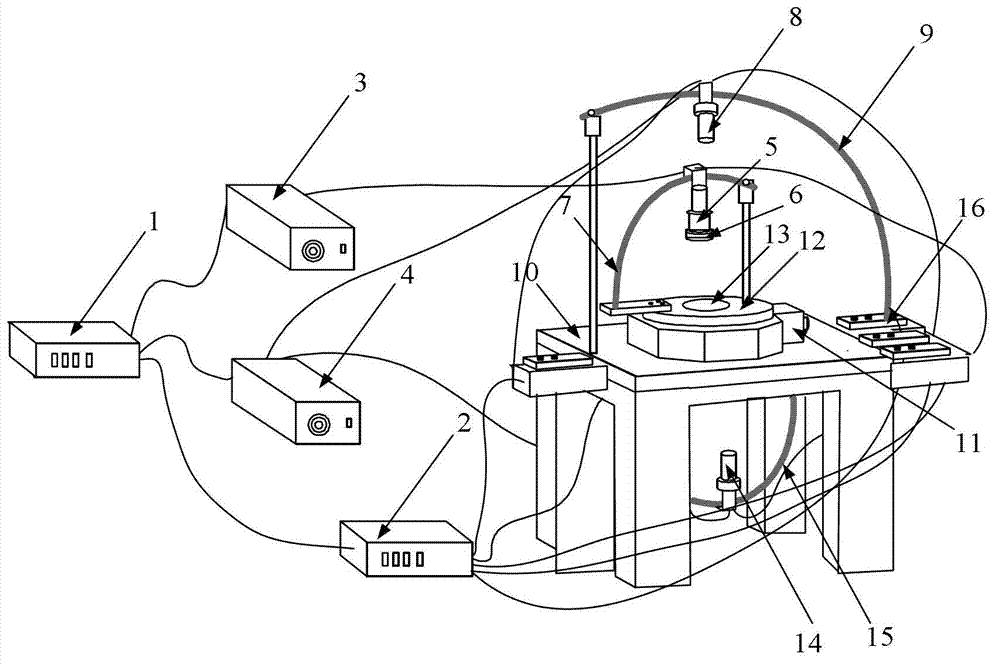
[0033] Specific implementation mode one: combine figure 2 Describe this embodiment, the measurement device for continuous spectrum bidirectional scattering distribution function described in this embodiment includes a control and data processor 1, a rotation controller 2, an illumination source generator 3, a dual-channel fiber optic spectrometer 4, and an illumination source probe 5 , Collimation amplification component 6, illumination light source probe bracket 7, reflected light receiving probe 8, reflection probe bracket 9, rotating platform 10, stepper motor 11 at the control end of the rotating table, rotating measuring table 12, sample ring 13, transmitting light receiving probe 14. Transmission probe bracket 15. Rotary platform control end stepper motor 16. Illumination light source probe end stepper motor, reflected light receiving probe end stepping motor, transmitted light receiving probe end stepping motor, illumination light source probe motion driver, reflected l...

specific Embodiment approach 2

[0037] Embodiment 2: This embodiment differs from Embodiment 1 in that the installation method of the motion driver of the illumination light source probe and the illumination source probe bracket 7 adopts the installation method of gear meshing. Other compositions and connection methods are the same as those in Embodiment 1.

specific Embodiment approach 3

[0038] Embodiment 3: This embodiment differs from Embodiment 1 in that the installation method of the reflective light receiving probe movement driver and the reflection probe bracket 9 adopts a gear meshing installation method. Other compositions and connection methods are the same as those in Embodiment 1.


PUM


Abstract

The invention provides a measuring apparatus for a continuous spectrum bidirectional scattering distribution function (BSDF), which relates to optical measurement equipment. The invention aims to overcome the problems of incapable measurement of the continuous spectrum BSDF, a narrow measurement spectral band, a small measurement angle and a low measuring speed. The rotating shaft of a rotating table board is connected with the motor shaft of a stepping motor; a sample ring is fixedly arranged at a through hole in the center of the rotating table board; a lighting source probe is fixedly arranged above the sample ring; a collimation amplifier assembly is fixedly arranged at a ray emitting lens of the lighting source probe; a reflection ray reception probe is installed above the sample ring, and a ray reception lens of the reflection ray reception probe faces the sample ring; a transmitted ray reception probe is fixedly arranged below the sample ring; a ray reception lens of the transmitted ray reception probe faces the sample ring; a ray signal input end of a control and data processor is connected with a ray signal output end of a two-channel fiber spectrometer. The measuring apparatus provided by the invention can be extensively used for measuring optical scattering characteristics of a material.

Description

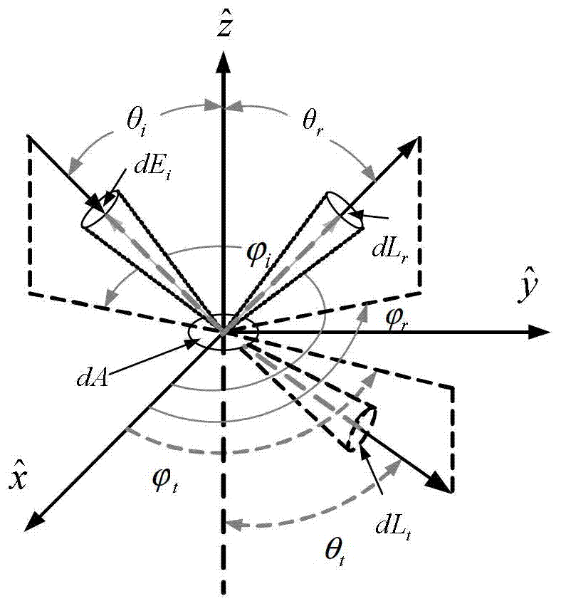
technical field [0001] The invention relates to optical measuring devices. Background technique [0002] Bidirectional Scattering Distribution Function (BSDF for short) is a physical quantity that describes the spectral reflection and transmission characteristics of various materials on the basis of radiometrics and geometric optics. It represents the reflection and transmission characteristics of materials at any observation angle under different incident angle conditions, such as figure 1 shown. [0003] Bidirectional scattering distribution function includes bidirectional reflection distribution function and bidirectional transmission distribution function, which is the only deterministic function describing the reflection and transmission characteristics of materials. [0004] The bidirectional reflection distribution function is defined as the ratio of the reflection radiance in a certain reflection direction to the incident irradiance incident on the surface of the m...

Claims


Application Information

Patent Timeline
IPC IPC(8): G01N21/25
Inventor 汪洪源刘彬张伟
Owner HARBIN INST OF TECH
Learn More