Locomotive resistance box

A resistance box and resistance technology, applied in the direction of resistors, electric vehicles, electrical components, etc., can solve the problem of easy burning of resistance boxes, and achieve the effect of reducing material consumption, reducing volume, and balancing heat generation

Inactive Publication Date: 2013-01-02
CRRC DALIAN CO LTD
View PDF3 Cites 3 Cited by
  • Summary
  • Abstract
  • Description
  • Claims
  • Application Information

AI Technical Summary

Problems solved by technology

[0005] The purpose of the present invention is to propose a locomotive resistance box for the problem of easy burnout in the existing locomotive resistance box, which realizes the advantages of not being easy to burn out, long service life, reducing the material consumption of the resistance band and the size of the resistance box

Method used


Image

  • Locomotive resistance box
  • Locomotive resistance box
  • Locomotive resistance box

Examples


Embodiment 1

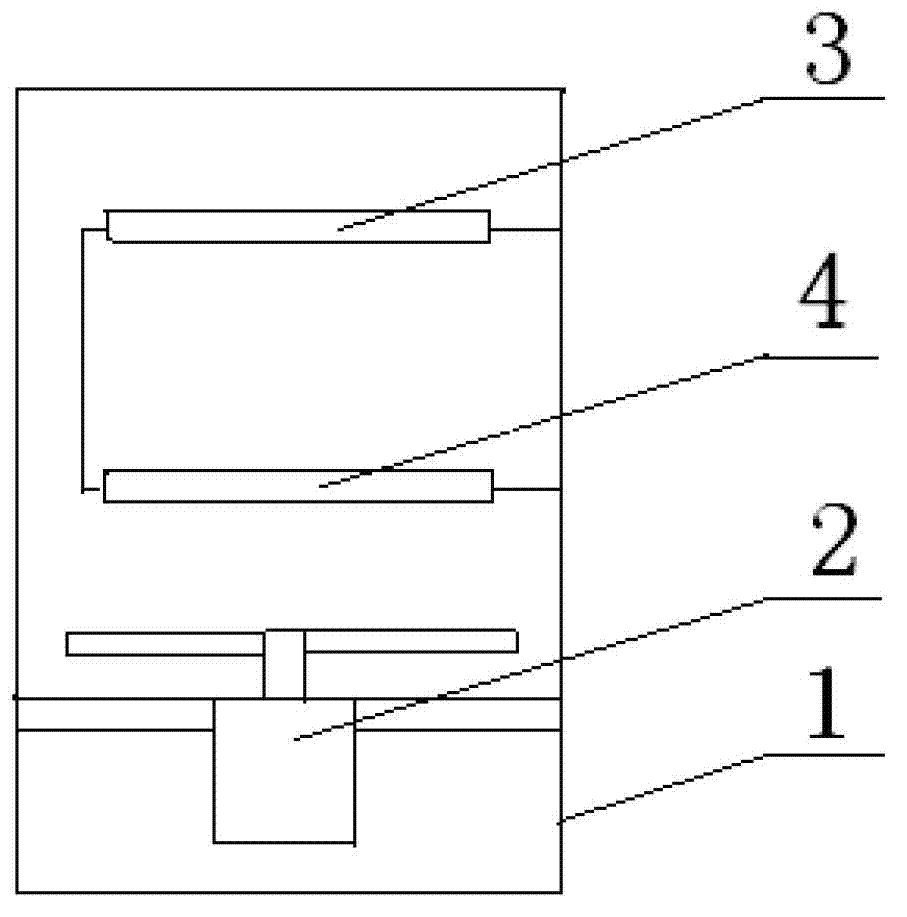
[0015] This embodiment discloses a locomotive resistance box, the appearance of which is the same as that of the existing locomotive resistance box structure, such as figure 1 As shown, it includes box 1, ventilator 2 and two resistance bands in series (the first resistance band and the second resistance band). , are respectively the first resistance surface 3 and the second resistance surface 4, the first resistance surface 3 and the second resistance surface 4 are parallel to each other, and are fixed in the box body 1; the fan 2 is fixed close to the second resistance surface 4 and away from the first resistance surface In the box on one side of the resistance surface 3, the air outlet direction of the fan 2 is perpendicular to the plane where the resistance surface (the first resistance surface 3 and the second resistance surface 4) is located. When the fan 2 is working, the air can be blown to the second A resistance surface 3 and a second resistance surface 4; the resist...

Embodiment 2

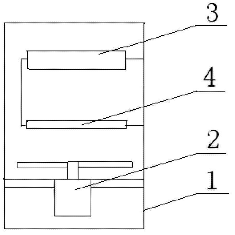
[0023] figure 2 It is a schematic structural diagram of the locomotive resistance box provided in Embodiment 2.

[0024] This embodiment discloses a locomotive resistance box, such as figure 2 As shown, the locomotive resistance box includes a box body 1, a ventilator 2 and two resistance bands connected in series. 4. The first resistance surface 3 and the second resistance surface 4 are parallel to each other and fixed in the box body 1; the fan 2 is fixed in the box body 1 close to the side of the second resistance surface 4 away from the first resistance surface 3 for ventilation The air outlet of the fan 2 is perpendicular to the plane where the resistance surface is located. When the fan 2 is working, the air outlet can blow to the first resistance surface 3 and the second resistance surface 4 at the same time; the resistance value of the resistance band of the second resistance surface 4 > the first The resistance value of the resistance band of the resistance surfac...

Embodiment 3

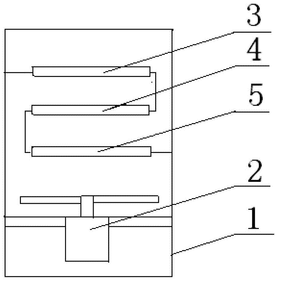
[0028] image 3 It is a schematic structural diagram of the locomotive resistance box provided in Embodiment 3.

[0029] This embodiment discloses a locomotive resistance box, such as image 3 As shown, the difference from Embodiment 1 is that the locomotive resistance box includes three resistance bands in series, and the three resistance bands are serpentinely wound into three resistance surfaces with gaps, which are respectively the first resistance surface 3 and the second resistance surface 4. The third resistance surface 5.

[0030]The ventilator 2 is fixed in the box body 1, and its vent faces the third resistive surface 5. When the ventilator 2 is working, its air outlet can blow to the first resistive surface 3 and the second resistive surface 4 at the same time; The resistance faces the direction away from the resistance surface of the ventilator 2, and the resistance value of the resistance band decreases gradually. The length and cross-sectional area of ​​each r...


PUM


Abstract

The invention provides a locomotive resistance box comprising a box body, a ventilation machine arranged in the box body, and more than two serial-connected resistance belts. The resistance belts are distributed in a snake shape, so as to form resistance surfaces with seams, and the resistance surfaces are parallel to one another; the ventilation machine is fixedly arranged at one side (close to the resistance surface at the outermost side and is far from the other resistance surfaces) of the box body; the air outlet direction of the ventilation machine is vertical to a plane of the resistance surfaces; and the resistance values of the resistance belts are gradually reduced in the direction from the resistance surface which is close to the ventilation machine to the resistance surface which is far from the ventilation machine. The locomotive resistance box provided by the invention has a simple, reasonable and compact structure, can solve the various defects of the conventional resistance box, and has the advantages of difficulty in burning, long service life, and capacity of reducing the material using amount of the resistance belts, and the size of the resistance box can be reduced.

Description

technical field [0001] The invention relates to electrical resistance equipment, in particular to a locomotive resistance box. Background technique [0002] The locomotive resistance box is widely used in the resistance braking and load test of the locomotive. Its function is to consume the electric energy generated by the locomotive during the resistance braking process or the load test process. It can be applied to various locomotives using resistance boxes for resistance braking or load testing. [0003] Existing resistance box structure such as figure 1 As shown, it includes: two series-connected and identical resistance bands arranged in the box body 1 and a fan 2 arranged under the two series-connected resistance bands. The two resistance bands are respectively arranged to form two with gaps. Resistance surface: the first resistance surface 3 and the second resistance surface 4, the air outlet direction of the fan 2 is perpendicular to the surface where the resistanc...

Claims


Application Information

Patent Timeline
IPC IPC(8): H01C13/02B60L7/02G01R1/20
Inventor 孔庆丰腾微朱军
Owner CRRC DALIAN CO LTD
Why Eureka
Try Eureka