Method and device for extending signal bandwidth in digital transmission system
A technology for signal extension and digital transmission, applied in the field of digital information transmission, it can solve the problems of limited bandwidth resources, single data type, and narrow data transmission rate variation range, so as to improve signal bandwidth, improve reliability, and reduce multipath fading. effect of influence
Active Publication Date: 2016-03-30
TIMI TECH +1
3 Cites 0 Cited by
AI-Extracted Technical Summary
Problems solved by technology
[0003] In general digital signal transmission, the bandwidth of the signal is fixed, which makes the range of data transmission rate narrow, and the type of data supported for transmission is relatively simple. Obviously, this cannot meet the needs of transmitting multiple data services in digital audio broadcasting systems.
However, t...
Method used
[0171] Using this method, the working frequency band of the wireless transmission system can be divided into multiple frequency bands with smaller bandwidths, wherein each frequency band is called a "subband" of the original working frequency band, and each subband can transmit data independently. When the data transmission rate needs to be increased, the signal bandwidth of a single data service can be increased by using multiple sub-bands for coordinated transmission at the...
Abstract
Proposed is a method for expanding signal bandwidth in a digital transmission system. The method includes the following steps: performing channel coding on service data, and allocating according to the spectrum mode used by a system the coded service data to one or more sub-bands designated by the spectrum mode; performing interleaving transformation in the time domain and frequency domain on the service data on the one or more sub-bands in units of interleaving blocks according to a multi-sub-band interleaving algorithm; performing sub-carrier modulation mapping on the interleaved service data in the order of the sub-bands according to the spectrum mode used by the system, and modulating the service data on each sub-band onto the signal of a corresponding sub-band frequency band; and sending the data on the signal of each sub-band frequency band. In addition, also proposed is a corresponding device for expanding signal bandwidth. Applying the method and device, each sub-band can transmit data alone. When it is necessary to improve the data transmission rate, by way of simultaneously using a plurality of sub-bands to perform transmission collaboratively, the signal bandwidth of a single data service is improved, effectively taking advantage of the limited bandwidth resources.
Application Domain
Error preventionMulti-frequency code systems +1
Technology Topic
Channel codeFrequency band +9
Image
Examples
- Experimental program(1)
Example Embodiment
[0018] Embodiments of the present invention are described in detail below, examples of which are shown in the drawings, wherein the same or similar reference numerals designate the same or similar elements or elements having the same or similar functions throughout. The embodiments described below by referring to the figures are exemplary only for explaining the present invention and should not be construed as limiting the present invention.
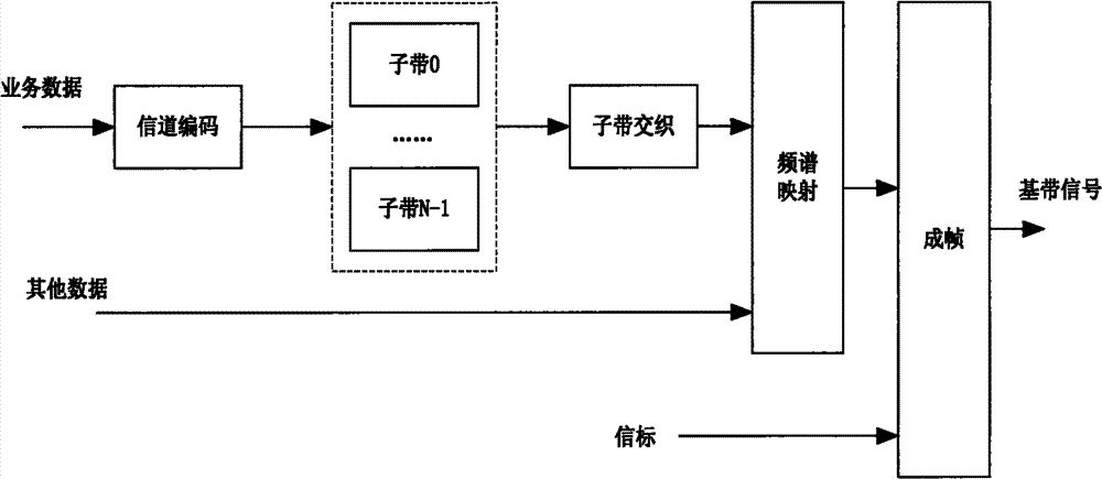
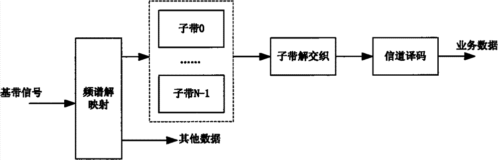
[0019] Referring to Figure 1, Figure 1a , Figure 1b Respectively show schematic diagrams of signal processing at the sending end and receiving end in the digital transmission system according to the present invention, which shows the processing process of the method for extending the signal bandwidth, including the following steps at the sending end: Step 1, channel coding the service data According to the spectrum mode used by the system, the coded service data is allocated to one or more subbands specified by the spectrum mode; step 2, according to the multi-subband interleaving algorithm, the one or more subbands are interleaved in units of interleaving blocks The business data on each sub-band is interleaved and transformed in the time domain and the frequency domain; step 3, according to the spectrum mode used by the system, the interleaved business data is subjected to sub-carrier modulation mapping in the order of the sub-bands, and the sub-bands on each sub-band are modulated and mapped. The service data is modulated onto the signal of the corresponding sub-band frequency band, wherein the sub-carrier modulation mode is any one of QPSK, 16QAM, 64QAM and other modulation methods; step 4, sending the data on the signal of each sub-band frequency band.
[0020] The spectrum mode is the distribution mode of each subband in the system on the working frequency band, including a class A spectrum mode and a class B spectrum mode; wherein the class A spectrum mode includes 8 subbands, and the nominal frequency points of the subbands are ±(i *100+50) kHz, i=0, 1, 2, 3; the type B spectrum mode includes 7 sub-bands, and the nominal frequency points of the sub-bands are ±i*100 kHz, i=0, 1, 2, 3.
[0021] like figure 2 Shows that the present invention allows the use of 39 spectrum modes and corresponding spectrum mode indices, where N I Indicates the number of interleaving blocks. The bandwidth of each spectrum in spectrum mode is 50kHz. In the spectrum mode, white blocks represent unoccupied spectrum, shaded blocks represent the lower half of an effective subband, and light gray represents frequency bands occupied by analog stations. Specifically:
[0022] The corresponding relationship between the spectrum mode index 1-39 and the subband occupied by the corresponding spectrum mode is as follows:
[0023] Spectrum mode index 1-8 is pure digital mode, spectrum mode index 9-21 is stereo FM simulcast mode, spectrum mode index 22-39 is mono FM simulcast mode; spectrum mode index 1, 3, 5, 7, 10, 14, 15, 18, 22, 24, 25, 26, 29, 30, 32, 33, and 38 are class B spectrum modes, and the rest of the indexes are class A spectrum modes; spectrum mode indexes 1-39 are related to the occupied subbands The corresponding relationship is as follows:
[0024] 01B4
[0025] 02A4A5
[0026] 03B3B4B5
[0027] 04A3A4A5A6
[0028] 05B2B3B4B5B6
[0029] 06A2A3A4A5A6A7
[0030] 07B1B2B3B4B5B6B7
[0031] 08A1A2A3A4A5A6A7A8
[0032] 09A3A4A5A6
[0033] 10B2B3B4B5B6
[0034] 11A3A4A5A6A7
[0035] 12A2A3A4A5A6
[0036] 13A2A3A4A5A6A7
[0037] 14B1B2B3B4B5B6
[0038] 15B2B3B4B5B6B7
[0039] 16A3A4A5A6A7A8
[0040] 17A1A2A3A4A5A6
[0041] 18B1B2B3B4B5B6B7
[0042] 19A2A3A4A5A6A7A8
[0043] 20A1A2A3A4A5A6A7
[0044] 21A1A2A3A4A5A6A7A8
[0045] 22B3B4B5
[0046] 23A3A4A5A6
[0047] 24B2B3B4B5
[0048] 25B3B4B5B6
[0049] 26B2B3B4B5B6
[0050] 27A2A3A4A5A6
[0051] 28A3A4A5A6A7
[0052] 29B1B2B3B4B5
[0053] 30B3B4B5B6B7
[0054] 31A2A3A4A5A6A7
[0055] 32B2B3B4B5B6B7
[0056] 33B1B2B3B4B5B6
[0057] 34A1A2A3A4A5A6
[0058] 35A3A4A5A6A7A8
[0059] 36A2A3A4A5A6A7A8
[0060] 37A1A2A3A4A5A6A7
[0061] 38B1B2B3B4B5B6B7
[0062] 39A1A2A3A4A5A6A7A8.
[0063] In particular, the step 2 also includes: sequentially selecting a section of specific service data symbols on each subband signal in each signal time period to form an interleaving block, so that each interleaving block includes multiple subbands and multiple The service data in the signal time segment satisfies the interleaving span in time and frequency; where the interleaving span in time and frequency can be changed according to system requirements, wherein the frequency span is determined by subband bandwidth and subband selection interval, and the time span is determined by subband The signal selection interval is determined.
[0064] image 3 It shows the extraction process of the interleaving block in the case that the subband interval and the signal time period interval are both 1, each square represents a subband, each row represents a time period, and the gray area forms an interleaving block, that is, the same number The set of positions for the defined interleaving block. That is to say, the selection is carried out according to the following method: assuming that there are n subbands on the i-th signal time period, the subcarrier matrix M is expressed as: M i ={M i,0 ,M i,1 ,...,M i,n-1}, the depth of the interleaving block is N s All the data of a subband in the time period, then the selection of the lth interleaving block is {M 0,l-1 ,M 1,l ,...,M Ns,mod(l-1+Ns,n)}. m i,j Indicates the data involved in interleaving contained in the jth subband in the ith time period, and the specific size is set in a specific system application.
[0065] In particular, in the OFDM symbol system, the one signal time period is one OFDM symbol. The service data is first channel coded, and according to the spectrum mode used by the system, the coded service data is allocated to one or more subbands specified by the spectrum mode; the data on multiple subbands is interleaved according to the multi-subband interleaving algorithm The service data on the one or more subbands is interleaved and transformed in the time domain and the frequency domain in units of blocks. The interleaved data is subjected to subcarrier modulation mapping in the order of subbands, where the subcarrier modulation mode is any one of QPSK, 16QAM, 64QAM and other modulation methods. The mapped sub-carrier signals are modulated onto OFDM symbols according to sub-bands, wherein the number of sub-carriers occupied by each sub-band on the OFDM symbols is equal. The system can fix the position of each subband on the OFDM symbol and the number of subcarriers according to actual application requirements. The data of each subband is sequentially modulated to the specified position on the OFDM symbol and after the current symbol is fully occupied, it is transferred to the next OFDM symbol.
[0066] On each subband of each OFDM symbol, a pilot signal is placed, and the relative position of the pilot information on each subband is the same, so as to ensure that each subband can be independently received. Its location is specifically determined during system design. Other digital transmission systems (such as MIMO systems) can use a similar method to fill the data to be sent to each subband. The signal composition of a multi-subband system can be composed of Figure 4 As shown, the signal composition under the OFDM symbol system is composed of Figure 5 Shows.
[0067] In OFDM symbology, the S N OFDM symbols form a logical subframe, and 4 logical subframes form a logical frame, S N Set the value for the system.
[0068] When selecting the interleaving block, it can be selected according to the following method, first construct a subcarrier matrix M of a frame, and the number of rows is 4*S N , the number of columns is N v *N I , the S N is the number of OFDM symbols in each subframe, the N v is the number of effective subcarriers contained in one subband in one OFDM symbol, the N I is the number of interleaving blocks; the number of rows and columns of the subcarrier matrix are counted from 1; the number of rows of the subcarrier matrix is divided into S from top to bottom and from left to right N , the number of columns is N v The submatrix M of s,t ,which is:
[0069] M = M 1,1 M 1,2 · · · M 1 , N I M 2,1 M 2,2 · · · M 2 , N I M 3,1 M 3,2 · · · M 3 , N I M 4,1 M 4,2 · · · M 4 , N I , in M s , t = ( m a , b ) s N × N v ,
[0070] m a,b (a=1,2,...S N , b=1, 2, ..., N v ) represents the data elements in the sub-matrix;
[0071] Assuming that there are n subbands on the i-th signal time segment, the subcarrier matrix is expressed as M i ={M i,0 ,M i,1 ,...,M i,n-1}, the depth of the interleaving block is N s All service data of a subband on OFDM symbols, then the selection of the lth interleaving block is {M 0,l-1 ,M 1,l ,...,M Ns,mod(l-1+Ns,n)}, where M i,j Indicates the data participating in the interleaving contained in the jth subband on the ith time period, where N s is the number of subcarriers included in one OFDM symbol.
[0072] 1) Record a certain row of the subcarrier matrix M as
[0073] M i = [ M i , 1 , M i , 2 , · · · , M i , N I ] = [ m 1 , i , 1 , m 2 , i , 1 , · · · m N v , i , 1 , m 1 , i , 2 , m 2 , i , 2 , · · · m N v , i , 2 , · · · , m 1 , i , N I , m 2 , i , N I , · · · m N v , i , N I ];
[0074] Among them, M i,l by M i Consecutive N in v component composition, m n,i,l for M i,l The components of , which in turn correspond to the elements in the i-th row, N v is the effective number of subcarriers included in a subband within a signal time period;
[0075] 2) to M i M in i,l (l=1, 2, ..., N I ) to replace the data elements of the business data, and get V i = [ VC i , 1 , · · · , VC i , N I ] = [ vc 1 , i , 1 , vc 2 , i , 1 , · · · , vc p , i , 1 , vc 1 , i , 2 , vc 2 , i , 2 , · · · , vc p , i , 2 , · · · , vc 1 , i , N I , vc 2 , i , N I , · · · , vc p , i , N I ] ;
[0076] Among them, VC i,j by V i Consecutive p components in the form, VC i,j =[vc 1,i,j , vc 2,i,j ,...,vc p,i,j ], vc h,i,j for VC i,j weight, Place M i,l The data elements of the business data in the Place M i,l The data element of the first business data in, p is N v Within each effective subcarrier, the number of data subcarriers for placing service data;
[0077] The corresponding relationship between l and j is:
[0078] j=((i-N SDISn -1-k*N SDISn )*(N I -1)+(l-1)) mod N I +1;
[0079] k=0, 1, 2, 3, which is the subframe sequence number;
[0080] i=k*S N +N SDISn +1, k*S N +N SDISn +2,...,(k+1)*S N;
[0081] N SDISn Set the value for the system;
[0082] 3) Take out V in sequence according to the row number i The jth subvector VC i,j , constructed as a one-dimensional vector B j = ( VC 1 , j , L VC 4 * ( S N - N SDISn ) , j ) , That is, the jth interleaving block;
[0083] to B j Interleave according to the interleaving algorithm, get where VC' i,j =[vc' 1,i,j , vc′ 2,i,j , L, vc′ p,i,j ];
[0084] The one-dimensional vector B' j (j=1, 2, L, N I VC' in ) i,j put into the matrix M i,l (l=1, 2, L, N I ), VC′ i,j The elements in are placed one by one in On the data elements of the business data in , namely vc' 1,i,j place The data element of the first business data in the
[0085] The corresponding relationship between l and j is:
[0086] j=((i-1)*(N I -1)+(l-1)) mod N I +1;
[0087] k=0,1,2,3.
[0088] The band interleaving algorithm includes: for the input sequence before interleaving where N MUX is the length of the interleaving block, the output sequence after interleaving is where z' n =z R(n) , R(n) is obtained as follows:
[0089] for(i=0, n=0; i
[0090] {
[0091] if(p(i) MUX )
[0092] {
[0093] R(n)=p(i);
[0094] n++;
[0095]}
[0096]}
[0097] where, p(0)=0, p(i)=(5×p(i-1)+q)mods, (i≠0), q=s/4-1.
[0098] That is to say: R(n) is obtained as follows:
[0099] P(0)=0, q=s/4-1;
[0100] p(i)=(5×p(i-1)+q) mods, (i≠0);
[0101] The initial value of n is 0, within the value range of 0≤i MUX ), then R(n)=P(i), and let n=n+1; otherwise, the obtained P(i) value is discarded, and the n value remains unchanged, and the subsequent calculated P(i) value is continued to be used Carry out conditional judgment until all R(n) values (0≤n≤N) are obtained MUX -1); N MUX Set the value for the system.
[0102] For the subcarrier matrix M can be constructed in the following way, in the subcarrier matrix M, in each submatrix M s,t Scattered Pilot Data Elements placed at a predetermined position; in the subcarrier matrix M, the submatrix M from the first column on the left 1,1 At the beginning, according to the sub-matrix order from left to right and from top to bottom, the data elements of the system information symbols carried by a subframe are repeated 3 times and collectively placed in one of the M s,t In the predetermined area; in the subcarrier matrix M, the submatrix M from the first column on the left 1,1 At the beginning, place the data elements of the service description information symbol carried by a frame in the order of left to right and top to bottom in M s,t 1st to Nth SDISn row and Nth SDISn +1 in row 1 to N SDISvalid column, and sequentially place the data elements of the service description information symbols carried by the logical frame in the order of the sub-matrix from top to bottom and from left to right, the N SDISvalid Set the value for the system; in the subcarrier matrix M, the submatrix M from the first column on the left 1,1 At the beginning, the data elements of the service data symbol carried by a frame are placed in M in order from left to right and top to bottom s,t The data elements of the service data symbols carried by the logical frame are sequentially placed in the residual position of the logical frame according to the order of the sub-matrix from top to bottom and from left to right.
[0103] Three transmission modes, as shown in Table 1.
[0104] Table 1: Transmission Mode System Parameters
[0105]
[0106] The subframe length is 160ms, 130560T;
[0107] In mode 1, the OFDM symbol data body length is 2.51ms, 2048T, the OFDM data body cyclic prefix length is 0.2941ms, 240T, the OFDM symbol period is 2.804, 2288T, the OFDM symbol subcarrier spacing is 398.4375Hz, and the beacon cyclic prefix length is 0.4706ms, 384T, the length of the beacon is 2.9804ms, 2432T, the subcarrier spacing of the beacon is 796.875Hz, and the number of effective subcarriers is N v is 242, Sn is 56;
[0108] In mode 2, OFDM symbol data body length is 1.255ms, 1024T, OFDM data body cyclic prefix length is 0.1716ms, 140T, OFDM symbol period is 1.426ms, 1164T, OFDM symbol subcarrier spacing is 796.8750Hz, beacon cyclic prefix length is 0.4069ms, 332T, the length of the beacon is 1.6618ms, 1356T, the subcarrier spacing of the beacon is 1593.75Hz, and the number of effective subcarriers is N v is 122, Sn is 111;
[0109] In mode 3, OFDM symbol data body length is 2.51ms, 2048T, OFDM data body cyclic prefix length is 0.0686ms, 56T, OFDM symbol period is 2.5786ms, 2104T, OFDM symbol subcarrier spacing is 398.4375Hz, beacon cyclic prefix length The length of the beacon is 0.2059ms, 168T, the length of the beacon is 2.7157ms, 2216T, the subcarrier spacing of the beacon is 796.875Hz, and the number of effective subcarriers is N v is 242, Sn is 61;
[0110] Wherein T is 1/816000 seconds, and the number of effective subcarriers in a subband is when the subcarriers in the upper half subband and the subcarriers in the lower half subband are not all virtual subcarriers, the effective subcarriers in the subband The number of carriers, when the subcarriers in the upper half subband or the lower half subband of a subband are virtual subcarriers, the effective number of subcarriers in this subband is N v /2.
[0111] System information is divided into system information 1 and system information 2 according to the different meanings they represent, each of which contains 72 bits, wherein according to different transmission modes, the data elements of the system information symbols are placed in the sub-matrix M s,t The location in Table 2 below. In one logical subframe, each 72 system information symbols of system information 1 and system information 2 are repeated three times, for example, in transmission mode 1, M s,t Place the 72 system information symbols of system information 1 and system information 2 in the positions specified in Table 8 in the 1st to 18th lines of , and place the same system information symbols in the designated positions of the 19th to 36th lines and the 37th to 54th lines respectively .
[0112] Table 2: The data elements of the system information symbols are placed in the sub-matrix M s,t position in
[0113] Transmission modes 1 and 3:
[0114]
[0115]
[0116] Transmission mode 2:
[0117]
[0118] Depending on the transmission mode, the data elements of the scattered pilots are placed in the sub-matrix M s,t The position of the middle row is transmission mode 1: rows 55-56; transmission mode 2: rows 109-111; transmission mode 3: rows 55-61; the data elements of the scattered pilots are placed in the sub-matrix M s,t The position b of the middle column is:
[0119] Transmission mode 1 and transmission mode 3:
[0120] Ifmod(a-1,3)==0
[0121] b = 12 p + 122 p = 0,1 , L , 10 12 p + 121 p = - 10 , - 9 , L , - 1,0
[0122] Ifmod(a-1,3)==1
[0123] b = 12 p + 126 p = 0,1 , L , 9 12 p + 117 p = - 9 , L , - 1,0
[0124] Ifmod(a-1,3)==2
[0125] b = 12 p + 130 p = 0,1 , L , 9 12 p + 113 p = - 9 , - 8 , L , - 1,0
[0126] Transmission mode 2:
[0127] Ifmod(a-1,3)==0
[0128] b = 12 p + 62 p = 0,1 , L , 5 12 p + 61 p = - 5 , - 4 , L , - 1,0
[0129] Ifmod(a-1,3)==1
[0130] b = 12 p + 66 p = 0,1,2,3,4 12 p + 57 p = - 4 , - 3 , - 2 , - 1,0 - - - ( 4 )
[0131] Ifmod(a-1,3)==2
[0132] b = 12 p + 70 p = 0,1,2,3,4 12 p + 53 p = - 4 , - 3 , - 2 , - 1,0
[0133] where 1≤a≤S N.
[0134] After scrambling, encoding, interleaving and constellation mapping, the service description information is placed in the M s,t Among the data elements specified on the M s,t See Table 3 for the location of data elements to place business description information. m s,t 1st to Nth in SDISn The data elements in the row are business description information, M s,t Nth SDISn +1 in row 1 to N SDISvalid The data element of is business description information. The service description information firstly organizes the subcarrier submatrix M from left to right and from top to bottom 1,1 After the data elements specified in Table 2 are filled, follow the Image 6 Arrows indicate directions to fill in corresponding data elements in each subcarrier submatrix in turn.
[0135] Table 3: N SDISn and N SDISvalid value
[0136]
[0137] In the sub-carrier matrix M, the data elements other than the service description information are placed to place the service data in a logical frame. The service data is first arranged from left to right and from top to bottom by subcarrier submatrix M 1,1 After the corresponding data elements are filled in, follow the Image 6 Arrows indicate directions to fill in corresponding data elements in each subcarrier submatrix in turn. Table 4 shows the four subcarrier submatrices in each transmission mode M 1 , j M 2 , j M 3 , j M 4 , j ( j = 1,2 , L , N I ) The number of data elements for placing business description information and the number of data elements for placing business data.
[0138] Table 4M 1,j m 2,j m 3,j m 4,j (j=1, 2, L, N I The number of data elements of business description information and the number of data elements of business data placed in )
[0139]
[0140] Interleave the data elements of the service data symbols placed in the sub-matrix, the interleaving is performed in units of interleaving blocks, for the length N of the interleaving blocks of transmission mode 1 and transmission mode 2 MUX For 46080, the interleaved block N of transmission mode 3 MUX has a length of 50688.
[0141] The above interleaving process is performed on each interleaving block, and after completion, each interleaving block is put back into the original subcarrier matrix according to the above method.
[0142] According to another embodiment of the present invention, a device for extending signal bandwidth in a digital transmission system is also provided, including the following modules: a channel coding module, configured to perform channel coding on service data;
[0143]The subband allocation module is used to allocate the coded service data to one or more subbands according to the spectrum mode used by the system; the subband interleaving module is used to divide all The business data on one or more sub-bands are interleaved and transformed in the time domain and frequency domain; the carrier modulation module performs sub-carrier modulation and mapping on the interleaved business data according to the order of the sub-bands according to the spectrum mode used by the system. The service data on each sub-band is modulated onto the signal of the corresponding sub-band frequency band; the transmission module is used to send the data on the signal of each sub-band frequency band.
[0144] The subband interleaving module is also used to sequentially select a section of specific service data on each subband signal in each signal time period to form an interleaving block, so that each interleaving block includes multiple subbands and multiple signal time periods Business data on the Internet to meet the interweaving span of time and frequency;
[0145] The time and frequency interleaving spans can be changed according to system requirements, wherein the frequency span is determined by the subband bandwidth and the subband selection interval, and the time span is determined by the subband signal selection interval.
[0146] The sub-band interleaving module selects the interleaving block as follows:
[0147] Construct a subcarrier matrix M of a frame, the number of rows is 4*S N , the number of columns is N v *N I , the S N is the number of signal time segments in each subframe, the N v is the effective number of sub-carriers contained in a sub-band within a signal time period, the N I is the number of interleaving blocks; the number of rows and columns of the subcarrier matrix are counted from 1; the number of rows of the subcarrier matrix is divided into S from top to bottom and from left to right N , the number of columns is N v The submatrix M of s,t ,which is:
[0148] M = M 1,1 M 1,2 L M 1 , N I M 2,1 M 2,2 L M 2 , N I M 3,1 M 3,2 L M 3 , N I M 4,1 M 4,2 L M 4 , N I , in M s , t = ( m a , b ) s N × N v ,
[0149] m a,b (a=1, 2, LS N , b=1, 2, L, N v ) represents the data elements in the sub-matrix;
[0150] Assuming that there are n subbands on the i-th signal time segment, the subcarrier matrix is expressed as M i ={M i,0 ,M i,1 ,...,M i,n-1}, the depth of the interleaving block is N s All the service data of a subband on signal time period, then the selection of the lth interleaving block is {M 0,l-1 ,M 1,l ,...,M Ns,mod(l-1+Ns,n)}, where M i,j Indicates the data participating in the interleaving contained in the jth subband on the ith time period, where N s is the number of subcarriers included in a signal time segment.
[0151] 1) Record a certain row of the subcarrier matrix M as
[0152] M i = [ M i , 1 , M i , 2 , · · · , M i , N I ] = [ m 1 , i , 1 , m 2 , i , 1 , · · · m N v , i , 1 , m 1 , i , 2 , m 2 , i , 2 , · · · m N v , i , 2 , · · · , m 1 , i , N I , m 2 , i , N I , · · · m N v , i , N I ];
[0153] Among them, M i,l by M i Consecutive N in v component composition, , m n,i,l for M i,l The components of , which in turn correspond to the elements in the i-th row, N v is the effective number of subcarriers included in a subband within a signal time period;
[0154] 2) to M i M in i,l (l=1, 2, ..., NI) replace the data elements of the business data to obtain V i = [ VC i , 1 , · · · , VC i , N I ] = [ vc 1 , i , 1 , vc 2 , i , 1 , · · · , vc p , i , 1 , vc 1 , i , 2 , vc 2 , i , 2 , · · · , vc p , i , 2 , · · · , vc 1 , i , N I , vc 2 , i , N I , · · · , vc p , i , N I ] ;
[0155] Among them, VC i,j by V i Consecutive p components in the form, VC i,j =[vc 1,i,j , vc 2,i,j ,...,vc p,i,j ], vc h,i,j for VC i,j weight, Place M i,l The data elements of the business data in the Place M i,l The data element of the first business data in, p is N v Within each effective subcarrier, the number of data subcarriers for placing service data;
[0156] The corresponding relationship between l and j is:
[0157] j=((i-N SDISn -1-k*N SDISn )*(N I -1)+(l-1)) mod N I +1;
[0158] k=0, 1, 2, 3, which is the subframe sequence number;
[0159] i=k*S N +N SDISn +1, k*S N +N SDISn +2,...,(k+1)*S N;
[0160] N SDISn Set the value for the system;
[0161] 3) Take out V in sequence according to the row number i The jth subvector VC i,j , constructed as a one-dimensional vector B j = ( VC 1 , j , · · · VC 4 * ( S N - N SDISn ) , j ) , That is, the jth interleaving block;
[0162] to B j Perform interleaving according to the interleaving algorithm to obtain where VC' i,j =[vc' 1,i,j , vc′ 2,i,j ,...,vc' p,i,j ];
[0163] The one-dimensional vector B' j (j=1, 2, ..., N I VC' in ) i,j put into the matrix M i,l (l=1, 2, ..., N I ), VC′ i,j The elements in are placed one by one in On the data elements of the business data in , namely vc' 1,i,j place The data element of the first business data in the
[0164] The corresponding relationship between l and j is:
[0165] j=((i-1)*(N I -1)+(l-1)) mod N I +1;
[0166] k=0,1,2,3.
[0167] In the subcarrier matrix M, in each submatrix M s,t Scattered Pilot Data Elements placed in the intended location;
[0168] In the subcarrier matrix M, the submatrix M from the first column on the left 1,1 At the beginning, according to the sub-matrix order from left to right and from top to bottom, the data elements of the system information symbols carried by a subframe are repeated 3 times and collectively placed in one of the M s,t in the predetermined area;
[0169] In the subcarrier matrix M, the submatrix M from the first column on the left 1,1 At the beginning, place the data elements of the service description information symbol carried by a frame in the order of left to right and top to bottom in M s,t 1st to Nth SDISn row and Nth SDISn +1 in row 1 to N SDISvalid column, and sequentially place the data elements of the service description information symbols carried by the logical frame in the order of the sub-matrix from top to bottom and from left to right, the N SDISvalid Set the value for the system;
[0170] In the subcarrier matrix M, the submatrix M from the first column on the left 1,1 At the beginning, the data elements of the service data symbol carried by a frame are placed in M in order from left to right and top to bottom s,t The data elements of the service data symbols carried by the logical frame are sequentially placed in the residual position of the logical frame according to the order of the sub-matrix from top to bottom and from left to right.
[0171] Using this method, the working frequency band of the wireless transmission system can be divided into multiple frequency bands with smaller bandwidths, each of which is called a "subband" of the original working frequency band, and each subband can transmit data independently. When the data transmission rate needs to be increased, the signal bandwidth of a single data service can be increased by using multiple sub-bands for coordinated transmission at the same time, so as to effectively use limited bandwidth resources; or when it is necessary to transmit multiple data services within the working frequency band at the same time , subbands can be assigned to different service types as required. The sub-band interleaving process designed according to the characteristics of multi-sub-band system and multi-path transmission can effectively reduce the influence of multi-path fading and improve the reliability of data transmission.
[0172] Although the embodiments of the present invention have been shown and described, those skilled in the art can understand that various changes, modifications and substitutions can be made to these embodiments without departing from the principle and spirit of the present invention. and modifications, the scope of the invention is defined by the appended claims and their equivalents.
PUM


Description & Claims & Application Information
We can also present the details of the Description, Claims and Application information to help users get a comprehensive understanding of the technical details of the patent, such as background art, summary of invention, brief description of drawings, description of embodiments, and other original content. On the other hand, users can also determine the specific scope of protection of the technology through the list of claims; as well as understand the changes in the life cycle of the technology with the presentation of the patent timeline. Login to view more.
Similar technology patents
Load balancing method and system applied to distributed application system
Owner:NAT UNIV OF DEFENSE TECH
High-reliability Bluetooth earphone wireless communication method
Owner:BESTECHNIC SHANGHAI CO LTD
Radar signal source system of frequency stepping system
InactiveCN108344977AIncrease signal bandwidthavoid spurious
Owner:INST OF ELECTRONICS CHINESE ACAD OF SCI
Distributed storage system
Owner:SKY PERFECT JSAT CORPORATION
Classification and recommendation of technical efficacy words
- Increase signal bandwidth
Radar signal source system of frequency stepping system
InactiveCN108344977AIncrease signal bandwidthavoid spurious
Owner:INST OF ELECTRONICS CHINESE ACAD OF SCI