Eureka AIR delivers breakthrough ideas for toughest innovation challenges, trusted by R&D personnel around the world.

Medical Instrument

A medical device and memory technology, which is applied in dissection devices, surgical device support, endoscopic cutting devices, etc., can solve problems such as difficult observation and inconvenient use, and achieve the effect of cost suppression and good visibility

Inactive Publication Date: 2013-01-02
中村正一 +1
View PDF0 Cites 6 Cited by
  • Summary
  • Abstract
  • Description
  • Claims
  • Application Information

AI Technical Summary

Problems solved by technology

[0005] However, in coronary artery bypass surgery, etc., due to the relationship between the position of blood vessel incision and the angle of insertion of the medical scalpel, Figure 7 That existing medical scalpel may cause the front end of the scalpel to be blocked by the operator's own hand. Therefore, in the above-mentioned medical scalpel 101 in which the grip portion 102 and the scalpel body 104 are arranged on a straight line, There is a problem that it is difficult to observe when cutting and it is inconvenient to use

Method used


Image

  • Medical Instrument
  • Medical Instrument
  • Medical Instrument

Examples


no. 1 approach 〕

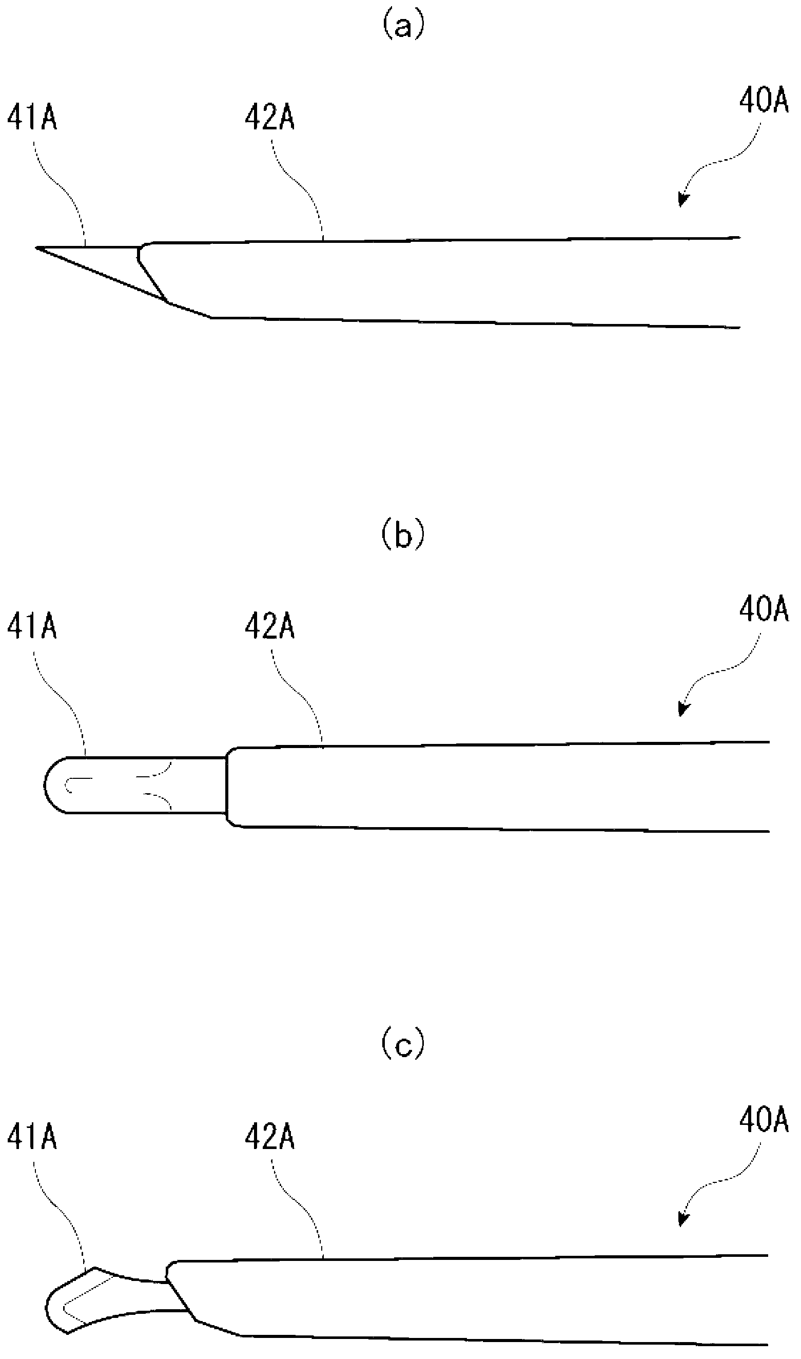
[0033] figure 1 It is an overall front view showing the outline of the medical device according to the first embodiment of the present invention. Such as figure 1 As shown, a medical device (here, a medical scalpel) 10A of the present embodiment includes a rod-shaped grip 20, a shape memory portion 30 connected to the front end of the grip 20, and a functional portion arranged at the front end of the shape memory 30 (in This is the scalpel body) 40A.

[0034] The grip part 20 is a part that is gripped by the user during use, and is a rod-shaped member made of metal such as titanium alloy or stainless steel. Knurling or sandblasting is performed on the periphery of the grip part 20 so that the user's finger does not slip easily during the grip operation.

[0035] The shape-memory part 30 is a rod-shaped member made of a shape-memory alloy such as Nitinol (nickel-titanium alloy) located at the tip of the grip part 20 . The so-called shape memory alloy is a special alloy th...

no. 2 approach 〕

[0053] However, the shape-memory alloy used in the shape-memory portion of the present invention is a special alloy that can return to the original shape after heating by heating even if it is deformed. However, if a large deformation exceeding the limit is applied, it cannot Return to its original shape. Therefore, it is necessary to consider not deforming the shape memory part beyond a certain range. Therefore, when it is desired to obtain a large angle of the functional part with respect to the grasping part, etc., and to set the functional part at an angle exceeding the deformation limit of the shape memory part, the medical device is configured as follows.

[0054] Image 6 It is an overall front view showing the outline of the medical device according to the second embodiment of the present invention. Additionally, for figure 1 The same parts are assigned the same symbols and detailed explanations are omitted.

[0055] Such as Image 6 As shown, the medical instrum...


PUM


Abstract

Provided is a medical instrument, wherein the functional part installed on the tip of the instrument can be made to be disposable by being made to be detachable and good visibility can be ensured by adjusting the angle thereof freely. In a medical instrument (10A) provided with a rod-shaped grip (20) at the base and a functional part (40A) on the tip that is used for the medical procedures, a shape memory part (30) obtained from a rod-shaped shape memory alloy is provided between the grip (20) and the functional part (40A). The grip (20), the functional part (40A), and the shape memory part (30) are made to be detachable from each other while the shape memory part (30) is trained as a straight line and the shape memory part (30) is bent for use as necessary. By heating the shape memory part (30) to the memory recovery temperature after use, the shape memory part (30) is returned to the original trained shape.

Description

technical field [0001] The present invention relates to medical instruments such as scalpels, reflectors, and traction hooks used in medical fields, and in particular to medical instruments capable of replaceably attaching and detaching functional parts located at the front ends of the instruments. Background technique [0002] Conventionally, a medical device having a rod-shaped grasping portion at the proximal end and a functional portion for medical actions such as a scalpel, a mirror, and a traction hook at the distal end generally arranges the grasping portion and the functional portion in a substantially straight line. [0003] Figure 7 and Figure 8 An example of such a conventional medical device is shown in . Figure 7 It is a schematic diagram showing an example of a conventional medical scalpel, Figure 8 It is a schematic diagram showing an example of a conventional medical mirror. [0004] Figure 7 The illustrated medical scalpel 101 has a rod-shaped grip po...

Claims


Application Information

Patent Timeline
Patent Type & Authority Applications(China)
IPC IPC(8): A61B17/3211A61B19/00A61B90/00
CPCA61B2017/00349A61B1/00A61B17/3211A61B2017/00464A61B2017/00946A61B17/00A61B2017/00867A61B17/22031A61B17/320016A61B19/26A61B90/50
Inventor 中村正一
Owner 中村正一
Why Eureka
Eureka Blog
Learn More