Conduit closing-in clamp and closing-in method

A fixture and conduit technology, applied in manufacturing tools, metal processing equipment, feeding devices, etc., can solve the problems of inability to meet the design requirements of high-precision parts, out-of-tolerance parts, and inability to repair, to improve the quality and the pass rate of closing , The idea is scientific and novel, and the effect of improving the precision of closing

Active Publication Date: 2015-01-07
SHENYANG LIMING AERO-ENGINE GROUP CORPORATION
View PDF6 Cites 0 Cited by
  • Summary
  • Abstract
  • Description
  • Claims
  • Application Information

AI Technical Summary

Problems solved by technology

[0002] Closing connection is one of the basic processes in the tube manufacturing process. This process is widely used in the manufacture of aero-engine tubes; however, for the closing connection of high-precision parts, there is a problem of out-of-tolerance parts after the closing connection
For example, in the production of the external oil return pipe of the rear bearing, the size design of the sphere is relatively strict, and the tolerance is only 0.047mm; and the surface of the bush is silver-plated, and the deformation of the sphere cannot be repaired. Grinding and repairing will damage the silver layer, and the silver layer of the bush cannot be damaged in the assembly Electroplating and repairing caused the size of the sphere to be out of tolerance, and a large number of parts were scrapped
Closing with the existing closing method cannot meet the design requirements of high-precision parts, so it is an urgent problem to be solved to study a new closing fixture and closing method

Method used


Image

  • Conduit closing-in clamp and closing-in method
  • Conduit closing-in clamp and closing-in method
  • Conduit closing-in clamp and closing-in method

Examples


Embodiment Construction

[0029] The present invention will be further described in detail below in conjunction with the accompanying drawings and specific embodiments.

[0030] Taking the oil return pipe externally connected to the bearing as an example, the closing fixture and closing method of the present invention will be described in detail.

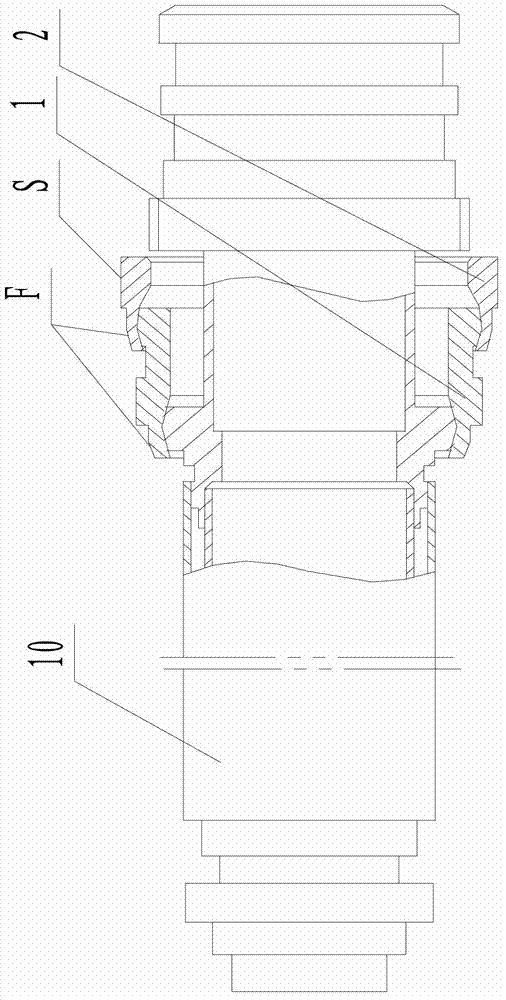
[0031] The oil return pipe externally connected to the rear bearing is composed of pipe joints and pipes through argon arc welding to form a conduit assembly 10. The combined welded conduit assembly 10 is divided into two parts to assemble the two bushings and press the ball to make it into one body. The oil return pipe is externally connected to the rear bearing. The structure is as figure 1 shown.

[0032] The outer surface of the two bushings has a silver-plated layer, and the coating is easily damaged when closing. After closing, the S dimension of the cylindrical surface of the second bushing 2 is easily deformed and out of tolerance. The cylindrical ...


PUM


Abstract

The invention discloses a conduit closing-in clamp and a closing-in method, belonging to the technical field of aero-engine manufacturing and machine manufacturing. The clamp comprises a first lining sleeve closing-in clamp and a second lining sleeve closing-in clamp, wherein the first lining sleeve closing-in clamp comprises a barrel, a mold block, a lining barrel and a sleeve; the outer surface of the mold block corresponds to the inner surface of the lining barrel; the inner surface of the mold block corresponds to the outer surface of the first lining sleeve; the inner surface of the lining barrel corresponds to the outer surface of one end of the barrel; a plug cover is arranged at the other end of the barrel; the second lining sleeve closing-in clamp comprises a barrel, a mold block, a lining barrel, a sleeve and a protecting sleeve; the outer surface of the mold block corresponds to the inner surface of the lining barrel; the inner surface of the mold block corresponds to the spherical surface of the second lining sleeve; the inner surface of the lining barrel corresponds to the outer surface of one end of the barrel; a plug cover is arranged at the other end of the barrel; and a through hole in one end of the protecting sleeve corresponds to the cylindrical surface of the second lining sleeve. According to the method disclosed by the invention, the protecting sleeve is adopted to control the deformation of the cylindrical surface and an adhesive tape is adopted to control the periphery deformation so as to prevent the surface damage of a plated layer.

Description

technical field [0001] The invention belongs to the technical field of aero-engine manufacturing and mechanical manufacturing, and in particular relates to a pipe closing fixture and a closing method thereof, which are suitable for the closing connection requirements of high-precision parts. Background technique [0002] Closing connection is one of the basic processes in the tube manufacturing process, and this process is widely used in the manufacture of aero-engine tubes; but for the closing connection of high-precision parts, there is a problem of out-of-tolerance parts after the closing connection. For example, in the production of the external oil return pipe of the rear bearing, the size design of the sphere is relatively strict, and the tolerance is only 0.047mm; and the surface of the bush is silver-plated, and the deformation of the sphere cannot be repaired. Grinding and repairing will damage the silver layer, and the silver layer of the bush cannot be damaged in t...

Claims


Application Information

Patent Timeline
Patent Type & Authority Patents(China)
IPC IPC(8): B21D43/00B21D39/00
Inventor 尹兰新周勇周京平王英冯大娟
Owner SHENYANG LIMING AERO-ENGINE GROUP CORPORATION
Why Eureka
Try Eureka