Orbital welding apparatus

A welding equipment, orbital technology, applied in the direction of welding equipment, welding equipment, auxiliary welding equipment, etc., can solve the problems of independent control, not allowing welding head speed/acceleration, etc.

Inactive Publication Date: 2013-01-09
J RAY MCCDERMOTT SA
View PDF7 Cites 26 Cited by
  • Summary
  • Abstract
  • Description
  • Claims
  • Application Information

AI Technical Summary

Problems solved by technology

This method allows simultaneous operation of multiple welding torches, but does not allow independent control of the speed / acceleration of each welding head

Method used


Image

  • Orbital welding apparatus
  • Orbital welding apparatus
  • Orbital welding apparatus

Examples


Embodiment Construction

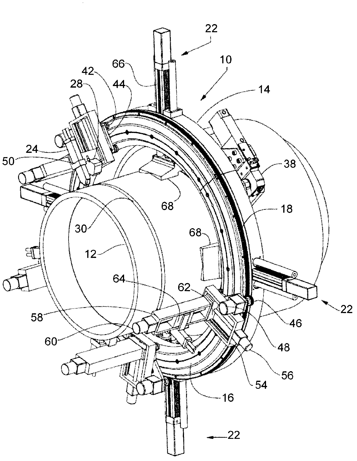
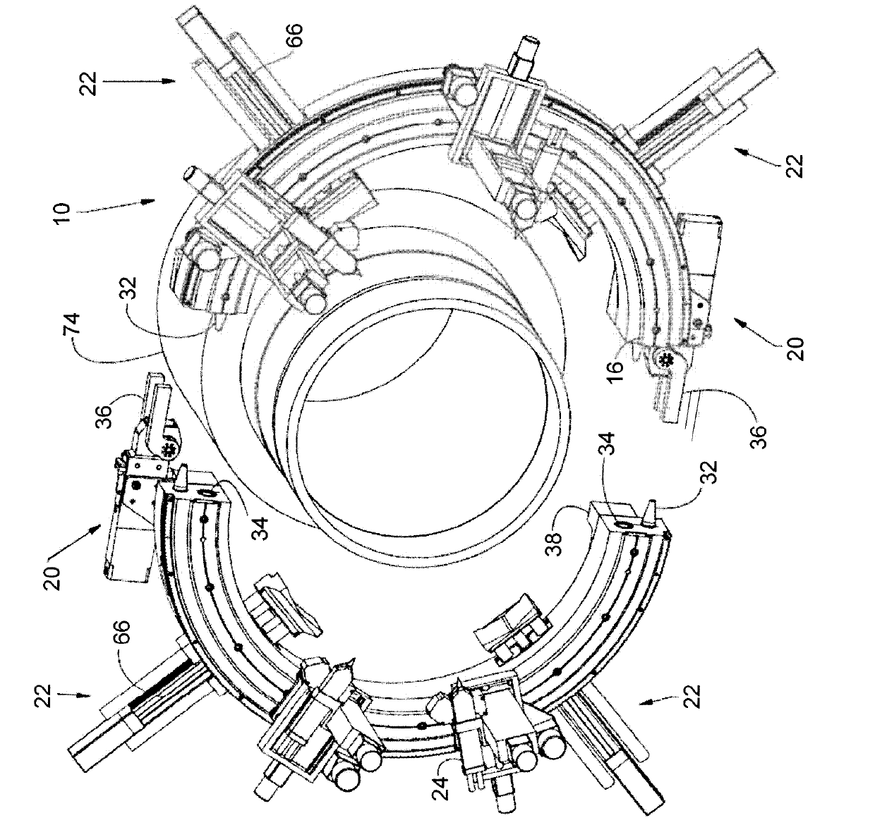
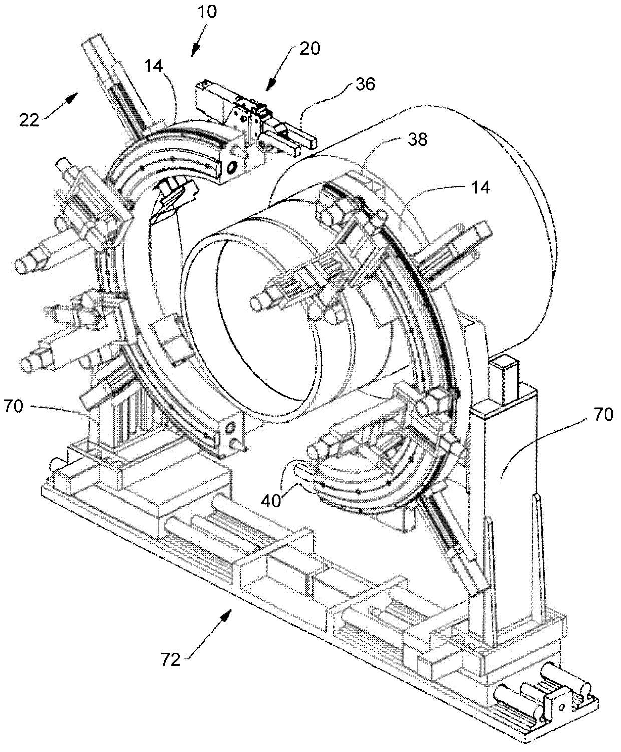
[0011] Such as figure 2 and image 3 As shown, the present invention is an orbital pipe welding apparatus 10 divided into two halves designed to orbit around figure 1 The pipe sections 12 are shown attached together. The orbital welding apparatus 10 generally includes two separate backing rings 14, a circular raceway 16, a circular ring gear 18, a locking device 20 for locking the two backing rings together, The device 10 in the welding position is fixed to and around the workpieces to be welded together (pipe sections 12), the device 22 is fixed around the workpieces to be welded together, the welding torch 24, the device 26 for holding the welding torch 24 and moving the welding torch 24 , and a scanning device 28 for scanning and tracking the welding area 30 .

[0012] Such as figure 2 and image 3 As shown, each collar 14 is semicircular and is provided with alignment means, such as a tapered pin 32 and a hole 34 for receiving said tapered pin 32 . This setting ens...


PUM


Abstract

A pipe welding arrangement that allows for real-time independent control of all carriages, torches, and ancillary components by design is provided. The approach uses a split-ring race that is mounted on a backing ring of similar design. Numerous welding heads are mounted on carriages that are distributed at set intervals along the circumference of the race. The left and right side race and backing ring assemblies are split at the twelve o'clock and six o'clock positions. They can be decoupled and spread apart horizontally to facilitate installation and for clearing obstacles. Alignment tools (tapered pins) acilitate assembly. Locking devices located near each split interface, coupled with the alignment pins, assure that the race acts as a continuous unit during the welding operation. Linear actuators mounted on the backing rings maintain concentricity between the race and the welded tube and act as a positive clamping system.

Description

technical field [0001] The present invention relates generally to automated pipeline welding processes and, more particularly, to the synchronized and independently controlled operation of multiple welding carriage / multiple torch arrangements. Background technique [0002] After years of development, pipeline welding technology has developed from manual welding to single-head semi-automatic orbital welding, and then to multi-head automatic welding. Each new approach brings improvements in quality and productivity. However, the state-of-the-art methods cannot reach their maximum theoretical potential due to the inability to independently control all parameters of the individual welding heads, especially velocity and acceleration. Also, these machines are not able to provide the clearance required for welding nozzles and other large accessories. [0003] An automated welding system typically includes one or more welding torches, a circular race coaxial with the pipes to be j...

Claims


Application Information

Patent Timeline
Patent Type & Authority Applications(China)
IPC IPC(8): B23K37/00B23K37/02
CPCB23K9/0286B23K9/0216B23K9/127B23K37/0276B23K2201/06B23K2101/06
Inventor P·J·伯巴科夫T·E·多伊尔C·D·诺埃尔T·L·布鲁
Owner J RAY MCCDERMOTT SA
Why Eureka
Try Eureka