Shelter lifting mechanism
A lifting mechanism and cabin technology, applied in the direction of lifting frame, lifting device, building structure, etc., can solve the problems of slow lifting speed, high cost, large processing volume, etc., and achieve high lifting efficiency, short operation time, and transmission speed. quick effect
- Summary
- Abstract
- Description
- Claims
- Application Information
AI Technical Summary
Problems solved by technology
Method used
Image

Examples
Embodiment 1
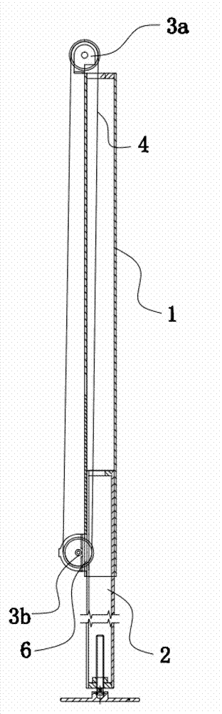
[0042] Such as figure 1 As shown, the shelter lifting mechanism in this embodiment includes a sleeve 1, and a movable support rod 2 sleeved inside the sleeve 1, wherein the sleeve 1 is used as a reference component for synchronous lifting with the shelter in the lifting mechanism, and the movable support Rod 2 is used to contact the ground and prop up the entire shelter lifting mechanism. There is a gap between the movable support rod 2 and the inner wall of the sleeve 1, and a driving device is arranged between the movable support rod 2 and the sleeve 1. It is used to drive the movable support rod 2 to move relative to the sleeve 1. More specifically, the driving device is used to drive the movable support rod 2 to be inserted into the sleeve 1 or protrude from the bottom of the sleeve 1, so as to realize the overall lifting mechanism. The change of the height, the sleeve 1 is provided with a first sprocket 3a and a second sprocket 3b, wherein the first sprocket 3a is located...
Embodiment 2
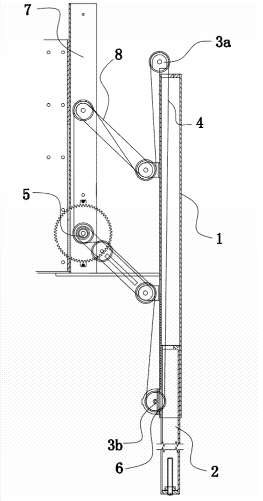
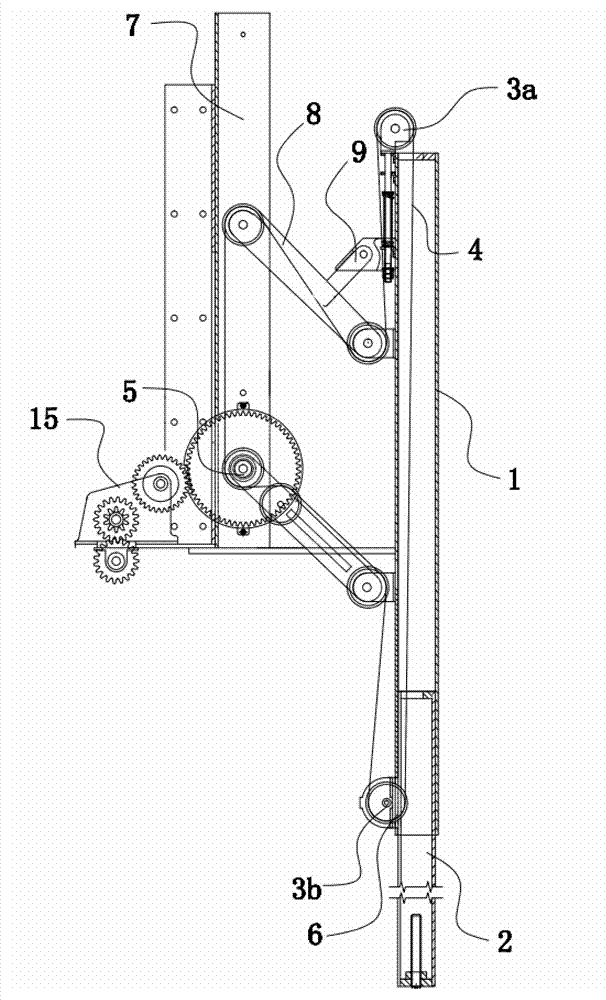
[0045] Such as figure 1 As shown, the shelter lifting mechanism of this embodiment is a further improvement of Embodiment 1. The driving device is a drive sprocket 5 provided with a power source, and the chain 4 is closed to form a chain ring. The chain ring is connected to the first sprocket 3a, the second chain The two sprockets 3b and the drive sprocket 5 are matched and connected and pre-tensioned, that is, the chain ring is surrounded and tensioned between the first sprocket 3a and the second sprocket 3b, through the normal rotation of the drive sprocket 5 and Reversed to realize the rise or fall of the part of the chain 4 located inside the sleeve 1 and used to drive the movable strut 2 up and down, thereby driving the movable strut 2 up and down. In this way, the tensioned chain 4 has a large driving torque, which makes it easier to lift and operate, and when the chain 4 is closed and rotated, the operation stroke is not limited by the length of the chain 4, and the str...
Embodiment 3
[0048] Such as figure 1 As shown, the shelter lifting mechanism of this embodiment is a further improvement of Embodiment 2, the first sprocket 3a is arranged on the top of the sleeve 1, the second sprocket 3b is arranged below the first sprocket 3a, On the outer wall of the sleeve 1, a chain inlet 6 for the chain 4 to penetrate is provided on the side wall of the sleeve 1. After the chain 4 bypasses the second sprocket 3b, it passes through the chain inlet 6 into the sleeve 1, and after bypassing the first sprocket 3a, go out from the opening at the top of the sleeve 1 to the outside of the sleeve 1, and cooperate with the driving sprocket 5 to form a chain ring. In this way, While realizing the lifting movable support rod 2, it is beneficial to the structural arrangement, the chains 4 are respectively arranged inside the sleeve 1, and the outer two sides are not easy to be entangled and interfere with each other.
[0049] Please refer to Embodiment 2 for other structures. ...
PUM
 Abstract
Description
Claims
Application Information
 - R&D
- Intellectual Property
- Life Sciences
- Materials
- Tech Scout
- Unparalleled Data Quality
- Higher Quality Content
- 60% Fewer Hallucinations
Browse by: Latest US Patents, China's latest patents, Technical Efficacy Thesaurus, Application Domain, Technology Topic, Popular Technical Reports.
© 2025 PatSnap. All rights reserved.Legal|Privacy policy|Modern Slavery Act Transparency Statement|Sitemap|About US| Contact US: help@patsnap.com