Dyeing vat

A dyeing vat and vat technology, which is applied in the field of dyeing vats, can solve the problems of high labor intensity for operators, uneven tension on fabrics, and inconsistent product quality, so as to achieve convenient operation for workers, convenient and labor-saving taking of yarns, and high product quality. Good results

Inactive Publication Date: 2013-01-09
CHANGZHOU POLYACE TEXTILE & YARN
View PDF2 Cites 7 Cited by
  • Summary
  • Abstract
  • Description
  • Claims
  • Application Information

AI Technical Summary

Problems solved by technology

It cannot solve the following two defects: (1) The materials to be dyed are relatively static in the dye vat, the dyeing time is long, and the dyeing uniformity is not high; Uneven yarn color elasticity, uneven dyeing, and inconsistent quality
It also cannot solve the problem of large internal pressure difference when a large number of materials to be dyed are printed and dyed
[0005] The structure of a kind of dyeing vat that is generally used now is: the skein cage of the dyeing vat includes a circular cage body, the upper part of the cage body is open, and a positioning shaft in the center of the cage body is arranged in the cage body and extends out of the upper part of the cage body. When putting the yarn material into the cage body directly from the upper opening of the cage body, the dye vat with this structure has the following defects: (1) There is no power source to drive the skein cage to move, and the cage body of the skein cage is still when working , so the yarn dyeing time is long, the production efficiency is low, and because the liquid does not generate agitation, it causes uneven dyeing yarn, uneven product quality, etc., uneven tension, slippery and other problems in the cloth, and poor product quality; (2 ) There is no separation in the cage. When dyeing the yarn, the yarns in the cage are squeezed and stacked together under the action of gravity, resulting in a dead corner of overlapping, which increases the pressure difference of the liquid on each part of the fabric, resulting in uneven dyeing and poor product quality. Unification and other problems are more serious; (3) The cage body is opened at the upper part, and the cage body is generally high, which brings inconvenience to the yarn taking and unloading, and the labor intensity of the operator is high

Method used


Image

  • Dyeing vat
  • Dyeing vat
  • Dyeing vat

Examples


Embodiment

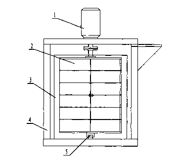
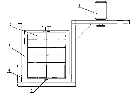
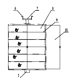
[0022] Such as Figure 1 to Figure 5 Shown, a kind of dye vat includes vat 3 and skeined sarong 2. The skein cage 2 is located in the cylinder body 3 , and the skein cage 2 includes a circular cage body 8 . The outside of the cylinder body 3 is provided with a frame 4 and a power source 1, the power source 1 is fixedly arranged on the frame 4, and the power source 1 is a motor. The upper end of the cage body 8 is provided with a flange 7 , and the upper end of the cage body 8 is also provided with a suspension hook 6 . A positioning shaft 5 is provided at the center of the outer bottom of the cage body 8 . The power source 1 is connected with the cage body 8 through the flange 7 at the upper end of the cage body 8 . One side of the circumference of the cage body 8 is provided with a door 10, and adopts a side door to facilitate taking yarn. The cage body 8 is further provided with at least one layer of horizontal partitions 9 separating the cage body 8 into relatively vert...


PUM


Abstract

The invention relates to a dyeing vat. The dyeing vat comprises a vat body (3) and a skein cage (2), the skein cage (2) is located in the vat body (3), the skein cage (2) comprises a circular cage body (8), a frame (4) and a power source (1) are arranged on the outside of the vat body (3), the power source (1) is arranged on the frame (4), a flange (7) is arranged at the upper end of the cage body (8), a locating shaft (5) is arranged in the middle of the bottom portion of the outside of the cage body (8), and the power source (1) is connected with the cage body (8) through the flange (7) at the upper end of the cage body (8). The skein cage can be driven by the power source to rotate around an axis of the locating shaft, yarns and the dyeing vat relatively move in the dyeing vat, dyeing time is greatly saved, dyeing effects are improved, production efficiency is greatly improved, and rotation of the skein cage enables liquid such as dye liquor to be stirred, so that yarn dyeing is even, product quality is unified, problems such as uneven tensile force borne by yarn materials are avoided, and the product quality is good.

Description

technical field [0001] The invention relates to a dye vat. The invention is mainly applicable to yarn dyeing and belongs to the technical field of printing and dyeing equipment. Background technique [0002] The existing yarn dyeing technology mainly puts the yarn to be dyed into the skein cage of the dyeing vat, and there is dye liquor in the dye vat, and the dye liquor contacts the yarn through the skein cage to realize the purpose of yarn dyeing. [0003] Chinese Patent Publication No. CN1090350A discloses an improved dye vat. The bottom of the vat is provided with a reversing valve and a bracket supporting the object to be dyed. The reversing valve and the bracket are supported by only one shaft. The rotation of the shaft realizes the reversing valve Towards. It cannot solve the following two defects: (1) The materials to be dyed are relatively static in the dye vat, the dyeing time is long, and the dyeing uniformity is not high; The back yarn color is uneven in elast...

Claims


Application Information

Patent Timeline
Patent Type & Authority Applications(China)
IPC IPC(8): D06B23/14
Inventor 罗坚平
Owner CHANGZHOU POLYACE TEXTILE & YARN
Why Eureka
Try Eureka