
High-speed pump

A technology for high-speed pumps and pump shafts, applied in the field of hydraulic pumps, can solve problems affecting the pumping efficiency and service life of plunger pumps, uneven oil film on the distribution surface, and prone to cavitation, so as to eliminate partial wear and avoid gas Corrosion phenomenon, the effect of uniform oil film

Inactive Publication Date: 2013-01-09
四川省宜宾普什驱动有限责任公司
View PDF15 Cites 9 Cited by
  • Summary
  • Abstract
  • Description
  • Claims
  • Application Information

AI Technical Summary

Problems solved by technology

However, the existing plunger variable pumps have poor oil absorption capacity and are prone to cavitation. The cover of the plunger pump is prone to inclination of the distribution surface under high-speed operation, resulting in uneven oil film on the distribution surface and eccentric wear on the high-pressure side. , affecting the pumping efficiency and service life of the plunger pump

Method used


Image

  • High-speed pump
  • High-speed pump
  • High-speed pump

Examples


Embodiment Construction

[0014] The present invention will be further described below in conjunction with accompanying drawing, protection scope of the present invention is not limited to the following:

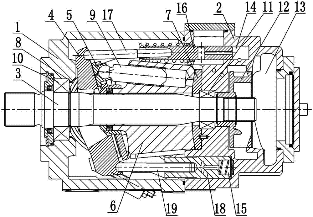
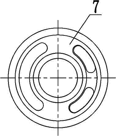
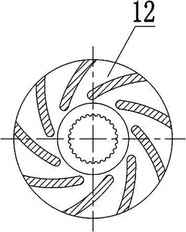
[0015] Such as figure 1 , figure 2 , image 3 As shown, a high-speed pump includes a casing 1, a pump cover 2, a pump shaft 3, a swash plate 4, a return plate, a sliding shoe 5, a cylinder body 6, a distribution plate 7, a split bearing 8, a plunger 9, a return Position piston rod 16, variable piston rod 18, last adjustment rod 17, lower adjustment rod 19, upper return spring, lower return spring and impeller 12.

[0016] The front part of the casing 1 has a shaft hole, the rear part of the casing 1 is connected to the pump cover 2, the pump shaft 3 extends into the inside of the casing 1 from the shaft hole, and one end is supported by the front bearing 10 outside the casing 1, and can be connected with external devices. Connection, liquid seal between the pump shaft 3 and the shaft hole; the ot...


PUM


Abstract

The invention discloses a high-speed pump which comprises a shell (1), a pump cover (2), a pump shaft (3), an inclined disc (4), a sliding shoe (5), a cylinder (6) and a distributing disc (7). The pump cover (2) is mounted at the rear of the shell (1), the pump shaft (3) is penetratingly arranged in the shell (1), the inclined disc (4), the sliding shoe (5), the cylinder (6) and the distributing disc (7) are sequentially mounted on the pump shaft (3), the sliding shoe (5) and the cylinder are in transmission via a plunger (9), the cylinder (6) is connected with the pump shaft (3) by an involute spline, and an impeller (12) is mounted at the rear end of the pump shaft (3) and is connected with the pump shaft (3) by an involute spline. The high-speed pump has the advantages that the impeller and the pump shaft rotate at the same speed, and the pressure of an oil outlet chamber of the impeller is increased along with increase of the rotational speed of the pump shaft, so that oil absorption capacity of the pump in a high-speed state is improved, and cavitation is effectively avoided; and the pump shaft is flexibly connected with the cylinder by the involute spline, eccentric wear of a high-pressure side is eliminated, reliability of the performance of a pump body is strengthened, and the service life of the high-speed pump is prolonged.

Description

technical field [0001] The invention relates to a hydraulic pump, especially a high-speed pump. Background technique [0002] As the active power pump in construction machinery and industrial systems, the plunger variable displacement pump has the characteristics of large volume, high efficiency and can be suitable for long-term work under high pressure and high speed. However, the existing plunger variable pumps have poor oil absorption capacity and are prone to cavitation. The cover of the plunger pump is prone to inclination of the distribution surface under high-speed operation, resulting in uneven oil film on the distribution surface and eccentric wear on the high-pressure side. , affecting the pumping efficiency and service life of the plunger pump. Contents of the invention [0003] The object of the present invention is to overcome the disadvantages of the prior art, and provide a high-speed pump with improved oil absorption capacity, effectively avoiding cavitati...

Claims


Application Information

Patent Timeline
IPC IPC(8): F04B1/20F04B53/00
Inventor 杨莽罗丽冯晓磊刘鸿刘猛
Owner 四川省宜宾普什驱动有限责任公司
Learn More