
Backlight module and display device

A technology for backlight modules and display devices, applied to lighting devices, fixed lighting devices, components of lighting devices, etc., can solve the problem of optical film colliding with the display panel, the display panel detaching from the carrying frame, and weakening the fixing effect of the display panel and the carrying frame and other issues to achieve the effect of ensuring display quality, good display quality, and reliable support

Inactive Publication Date: 2013-01-09
AU OPTRONICS CORP
View PDF5 Cites 12 Cited by
  • Summary
  • Abstract
  • Description
  • Claims
  • Application Information

AI Technical Summary

Problems solved by technology

However, as the size of the display device shrinks, the area between the carrying frame and the display panel where the frame glue can be attached becomes smaller, which weakens the fixing effect between the display panel and the carrying frame.
At this time, since the optical film below the display panel is a free body, the optical film may collide with the upper display panel during the strength test or use, causing the display panel to detach from the supporting frame

Method used


Image

  • Backlight module and display device
  • Backlight module and display device
  • Backlight module and display device

Examples


Embodiment Construction

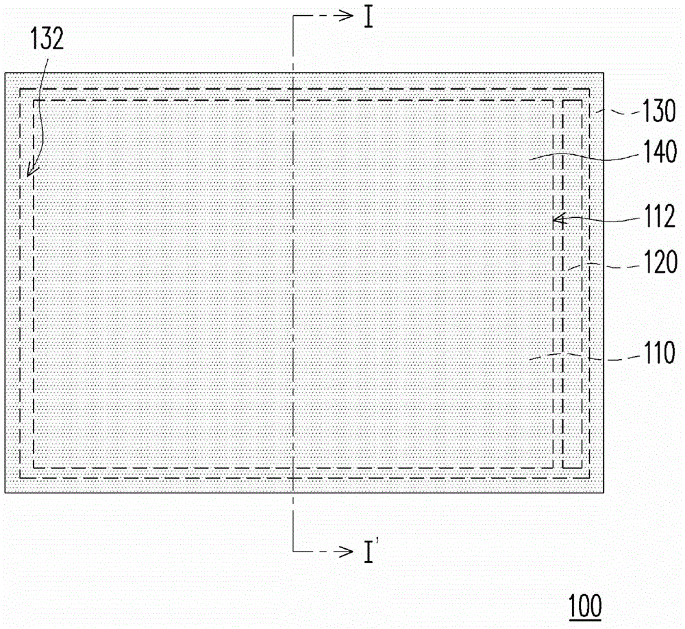
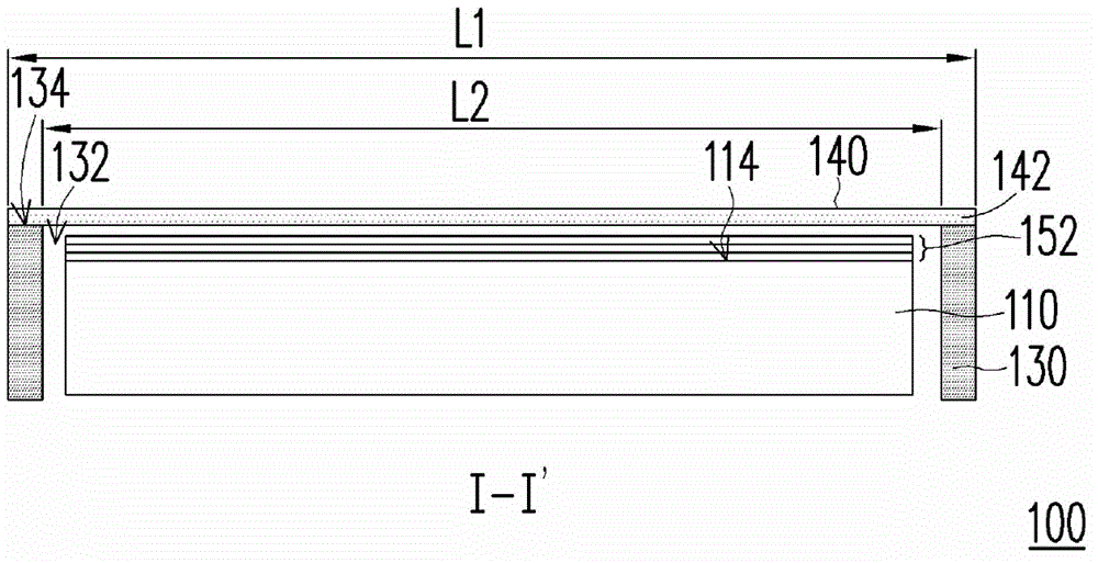
[0035] Figure 1A It is a top view of a backlight module according to an embodiment of the present invention. Figure 1B for Figure 1A The cross-sectional view of the backlight module along the line I-I'. Such as Figure 1A and 1B As shown, the backlight module 100 includes a light guide plate 110 , a light emitting element 120 , a supporting frame 130 and a transparent film 140 . The light guide plate 110 has a light incident surface 112 and a light exit surface 114 , and the light emitting element 120 is disposed beside the light incident surface 112 . Here, the light emitting element 120 is, for example, a light emitting diode (LED light bar), a cold cathode fluorescent lamp (CCFL) or other suitable light emitting elements, for emitting light, entering the light guide plate 110 through the light incident surface 112 , and passing through The light emitting surface 114 emits out of the light guide plate 110 . The carrying frame 130 surrounds the light guide plate 110 and...


PUM


Abstract

The invention relates to a backlight module which comprises a light guiding plate, a light emitting element, a bearing frame, and a light transmitting film. The light guiding plate comprises a light entering surface and a light exiting surface. The light emitting element is disposed beside the light entering surface, and is suitable for emitting light which passes through the light entering surface, enters the light guiding plate, and exits the light guiding plate through the light exiting surface. The bearing frame is disposed at the periphery of the the light guiding plate so as to form an opening exposing the light exiting surface, and has a top surface. The light transmitting film is disposed on the bearing frame, and the periphery of the light transmitting film is attached to the top surface of the bearing frame to seal the opening. The invention also provides a display device using the backlight module, wherein a display panel is disposed on the light transmitting film.

Description

technical field [0001] The invention relates to a light source module and its application, in particular to a backlight module and a display device using the backlight module. Background technique [0002] Nowadays, liquid crystal display devices are widely used in the display of consumer electronic products such as mobile phone (mobile phone), notebook computer (notebook personal computer), personal computer (personal computer, PC) and personal digital assistant (personal digital assistant, PDA). on the screen. However, since the liquid crystal display panel (LCD panel) of the liquid crystal display device itself does not have the function of emitting light, it is necessary to configure a backlight module under the liquid crystal display panel to provide the required backlight for displaying on the liquid crystal display panel. [0003] In existing backlight modules, an optical film is provided above the light guide plate to increase optical performance or provide optical ...

Claims


Application Information

Patent Timeline
IPC IPC(8): F21S8/00F21V17/00F21V13/00G02F1/13357
Inventor 陈群元
Owner AU OPTRONICS CORP
Learn More