
Device for measuring oblique projection of glass mold die cavity bottom groove

A technology of glass molds and bottom grooves, which is applied in the direction of measuring devices, mechanical measuring devices, and mechanical devices, etc., can solve problems such as successful applications in the industry that have not been heard of, and technical inspirations that have not been seen, so as to meet the detection speed requirements and reduce operations. intensity effect

Inactive Publication Date: 2013-01-09
ORI MOLD TECH SUZHOU
View PDF5 Cites 3 Cited by
  • Summary
  • Abstract
  • Description
  • Claims
  • Application Information

AI Technical Summary

Problems solved by technology

[0003] When processing glass molds, that is, forming molds, it is necessary to accurately measure the oblique height of the mating groove of the bottom mold to ensure that the cooperation between the forming mold and the bottom mold meets the design requirements of the drawings. There are technologies that use random inspection to detect the height of the inclination of the matching groove of the bottom mold. The detection method is the projection detection method. Although the projection detection method can meet the detection requirements, it has the following two deficiencies: one is that the projector needs to be placed outside the production line. On-site places, so it is troublesome to carry the glass molds for sampling inspection, and the labor intensity of the inspectors is high. When the instrument detects the inclination height of the mating groove of the bottom mold, it needs to find a surface as a reference, and the time it takes to determine the reference surface is usually more than 3 minutes, so the efficiency is low
[0004] If you want to get rid of the above-mentioned unfavorable factors of the measurement of the oblique height of the mating groove of the bottom mold by the projection method, unless you design a reasonable detection device, but in the so far disclosed There is no corresponding technical revelation in patent and non-patent literature, and there is no relevant information about successful application in the industry

Method used


Image

  • Device for measuring oblique projection of glass mold die cavity bottom groove
  • Device for measuring oblique projection of glass mold die cavity bottom groove

Examples


Embodiment 1

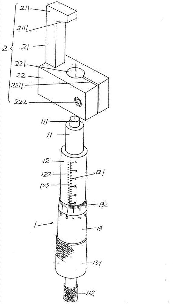
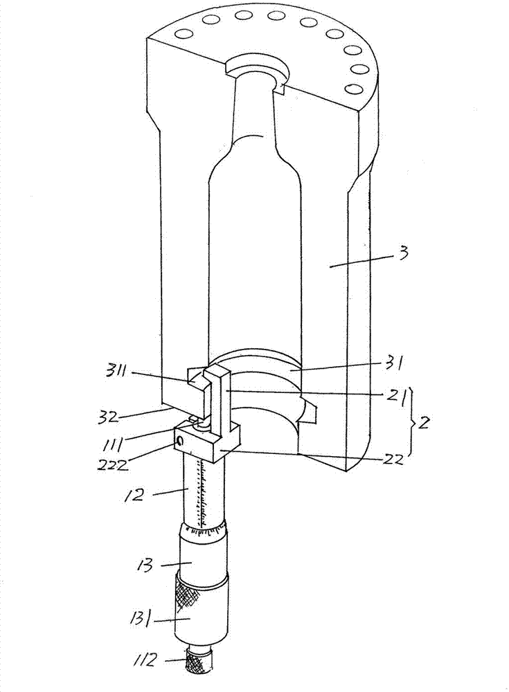
[0011] See figure 1 , provides a known micrometer 1 composed of a micrometer screw 11, a fixed sleeve 12 matched with the micrometer screw 11, and a micrometer cylinder 13 matched with the fixed sleeve 12 and having a micrometer cylinder knob 131, The micrometer 1 of this kind of structure can be purchased from commercially available channels, for example, preferably but not limited to, the model SHJX-2A-micrometer produced by China Shanghai Jinxin Measuring Tools and Cutting Tools Co., Ltd. and sold before the application is proposed . There are scale marks 121 at intervals of 1 mm on the aforementioned fixed sleeve 12 , and there are second scale marks 122 at intervals of 0.5 mm at positions corresponding to adjacent first scale marks 121 . at present figure 1 The position state shown is an example, the first scale marking line 121 is located on the right side of the height direction of the fixed sleeve 12, while the second scale marking line 122 is located on the left sid...


PUM


Abstract

The invention provides a device for measuring the oblique projection of a glass mold die cavity bottom groove, belonging to the technical field of a detecting apparatus for machining a glass mold. The device comprises a micrometric screw, a fixed sleeve pipe and a micrometer gauge. The device is characterized by further comprising a bottom groove oblique projection matching gauge, wherein the bottom groove oblique projection matching gauge comprises a single-foot ruler and a ruler base, the single-foot ruler is formed at one end of the rule base, the upper end of the single-foot ruler is formed into a ruler foot, one side of the ruler foot, which faces the ruler base, is formed into a reference inclined surface, a fixed hole is arranged in the rule base, the fixed hole extends to be provided with a clamping groove, a clamping screw is arranged on the rule base, the micrometric screw stretches into the fixed hole, the upper end face of the micrometric screw extends to be provided with a measuring anvil, the measuring anvil stretches out of the fixed hole, and the lower end of the micrometric screw is provided with a force measuring knob. The device has the advantages that the device can be used for detecting in the production field without carrying a glass mold by testers, so that the work strength of the testers can be reduced; and the device is simple in structure, easy to carry, and quick and exact to detect without needing to search a reference surface, so that the detection speed requirement of the industrially produced glass mold can be met.

Description

technical field [0001] The invention belongs to the technical field of detection instruments for glass mold processing, and in particular relates to a device for measuring the inclination position of the bottom groove of a glass mold cavity. Background technique [0002] In the manufacturing process of the glass mold, it is necessary to process the matching groove of the bottom mold in the lower part of the mold cavity of the glass mold (that is, the forming mold, the same below), so that the bottom mold can cooperate with it. The quality of the effect will affect the quality of glass containers such as bottles. Therefore, the industry usually regards the matching groove of the bottom mold of the glass mold and the matching state of the bottom mold as an important indicator for checking whether the glass mold meets the quality. [0003] When processing glass molds, that is, forming molds, it is necessary to accurately measure the oblique height of the mating groove of the bo...

Claims


Application Information

Patent Timeline
IPC IPC(8): G01B5/02
Inventor 戈剑鸣
Owner ORI MOLD TECH SUZHOU
Learn More