
Superimposed large-current bias alternative-current (AC) current measuring device

A technology of large DC bias and AC current, applied in measuring devices, measuring electrical variables, measuring current/voltage, etc., can solve the problems of inability to measure small AC signals, insufficient resolution, and large Hall sensors.

Active Publication Date: 2013-01-09
BEIJING DONGFANG MEASUREMENT & TEST INST
View PDF6 Cites 12 Cited by
  • Summary
  • Abstract
  • Description
  • Claims
  • Application Information

AI Technical Summary

Problems solved by technology

The structure of the Hall sensor is simple, the accuracy and linearity of the measurement results are high, and it can measure the current of DC, AC and various waveforms. It seems to meet the needs of measuring small AC signals with large DC bias superimposed, but the analysis It has the following disadvantages: ①Its frequency band is not wide enough, and the Hall devices with relatively wide bandwidths available on the market are about 0 to 200kHz; ②The full range of Hall sensors is generally relatively large (such as tens of Amperes), the resolution of small-amplitude currents (such as a few milliamps) is not enough. Compared with large DC, small AC signals are much smaller, so the measured AC part is very inaccurate and has a large error
Because magnetic materials can only transmit coupled AC signals and cannot transmit DC signals, only AC currents can be measured
If a traditional current transformer directly measures a small AC signal superimposed with a large DC bias, the large DC will saturate the magnetic core and lose the effect of coupling the AC signal, so it is impossible to measure a small AC signal superimposed with a large DC bias. Purpose

Method used


Image

  • Superimposed large-current bias alternative-current (AC) current measuring device
  • Superimposed large-current bias alternative-current (AC) current measuring device
  • Superimposed large-current bias alternative-current (AC) current measuring device

Examples


Embodiment Construction

[0022] Embodiments of the present invention will be described in further detail below in conjunction with the accompanying drawings.

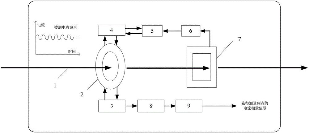
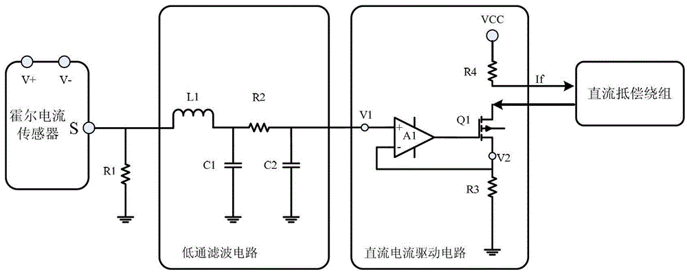
[0023] like figure 1As shown in FIG. 1 , it is a structural schematic diagram of a measuring device for superimposing an AC current with a large DC bias in the present invention. Including a current transformer, the closed magnetic core 2 of the current transformer is respectively wound with a secondary induction winding 3 with a number of turns N2 and a DC compensating winding 4 with a number of turns N1, and the measured current 1 is used as the primary current of the transformer from the magnetic The center of the core passes through, and the DC compensation winding 4 is connected to the DC current measuring device 7 through the sequentially connected DC current drive circuit 5 and the low-pass filter circuit 6. The DC current measuring device 7 converts the measured current signal into a voltage signal, and passes through the low-pass Afte...


PUM


Abstract

The invention provides a superimposed large-current bias alternative-current (AC) current measuring device, which aims at measuring small AC current which is superimposed on large-current bias, is wide in measurement frequency range and capable of accurately measuring a small AC signal under the situation of the large-current bias. The measuring device comprises a current transformer and a direct-current (DC) current measuring device, wherein a closed magnetic core of the current transformer is respectively wound with secondary sensing windings with turns of N2 and DC compensation windings with turns of N1, and the measured current is used as primary current of the transformer to run through the center of the magnetic core; and the DC compensation windings are connected with a DC current measuring device through a DC current drive circuit and a low-pass filter circuit, which are sequentially connected with each other, the DC current measuring device converts the measured current signal to an electric signal, after the AC component is filtered by the low-pass filter circuit, one DC current which can counteract the magnetic sensing strength produced by the DC bias current in the current transformer is outputted through the DC current drive circuit.

Description

technical field [0001] The invention relates to the technical field of current measurement, in particular to a measuring device for superimposing an alternating current with a large direct current bias. Background technique [0002] How to measure current accurately and conveniently has always been a subject of continuous exploration in the field of current measurement. Connect a small resistor (shunt) in series in the measurement circuit, measure the voltage across the shunt, and use Ohm’s law I=U / R to divide the measured voltage by the resistance of the shunt to calculate the required current. value. This measurement method uses less equipment, is convenient and quick, and has been generally welcomed. However, when this method needs to measure the AC current superimposed with a large DC bias, it will have the following disadvantages. First, it is not isolated from the measurement circuit, and there are certain safety hazards. If additional isolation measures are added, t...

Claims


Application Information

Patent Timeline
IPC IPC(8): G01R19/00
Inventor 梅高峰刘民张若林金光远郝慧萍
Owner BEIJING DONGFANG MEASUREMENT & TEST INST
Learn More