
High energy beam processing method with ejection point as control target

A processing method and technology of control target, applied in the direction of digital control, electrical program control, etc., can solve the problems such as the inability to synchronously turn the flow beam, the shape error of the slit, the reduction of the cutting ability, etc., to eliminate the uncut triangle area and eliminate the shape error. , Improve the effect of cutting efficiency

Active Publication Date: 2013-01-09
柔锋机械科技(江苏)有限公司
View PDF4 Cites 7 Cited by
  • Summary
  • Abstract
  • Description
  • Claims
  • Application Information

AI Technical Summary

Problems solved by technology

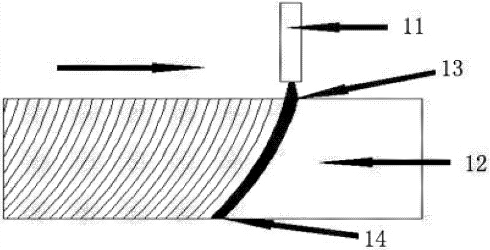
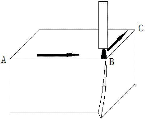
[0004] Defect 1: When the cutting direction needs to be changed when cutting to the corner, due to the lag of the stream injection point, the stream cannot be turned synchronously up and down, resulting in shape error at the corner (such as Figure 2)
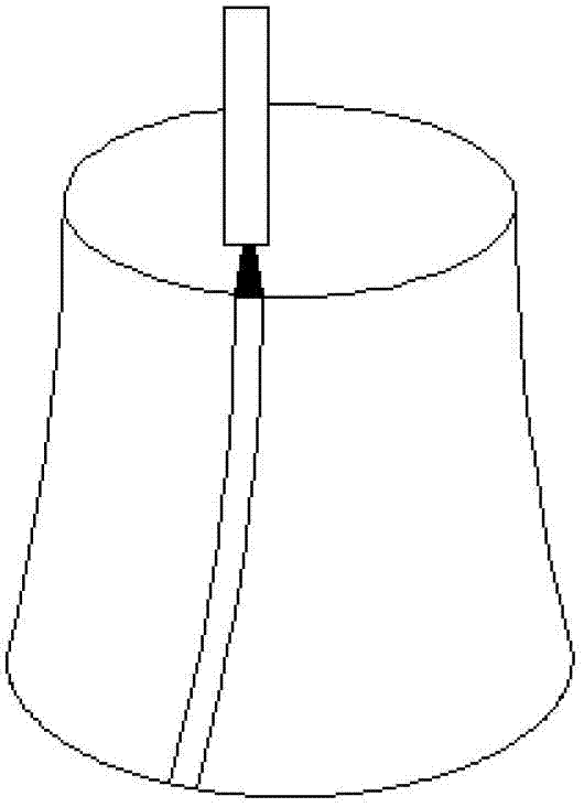
[0005] Defect 2: When cutting an arc, the cutting direction needs to be changed at any time. Due to the lag of the jet exit point, the up and down stream cannot be turned synchronously, resulting in a small arc. The shape error (such as Figure 3)
[0006] Defect 3: When the flow beam interacts with the material, the upper part of the material to be cut near the injection point, due to the high energy of the flow beam, the material can be quickly cut off, However, as the cutting depth increases, the energy of the stream gradually decays, and the cutting ability decreases
Due to the above reasons, the flow pattern of the stream at the injection point is different from that at the exit point, resulting in a shape error of the slit cut by the stream (such as Figure 4)
[0007] Defect 4: When the high-energy beam cuts the material, a small uncut triangular area ( As shown in Figure 5)
Although the above two methods partially solve the problem of the shape error of the cut piece in some aspects, the above two methods do not realize that the main cause of the shape error is the injection point rather than the injection point. Therefore, the above methods cannot be corrected. Error elimination forms a complete solution, and it is difficult to fundamentally and effectively solve the shape error problem of high-energy beam cutting

Method used


Image

  • High energy beam processing method with ejection point as control target
  • High energy beam processing method with ejection point as control target
  • High energy beam processing method with ejection point as control target

Examples


Embodiment

[0121] The material of the workpiece is: stainless steel 304 with a thickness of 10mm;

[0122] The cutting pattern is a square IJGH with a side length of 100mm, and there is a circle with a diameter of 50mm inside the square IJGH, such as Picture 12 Shown

[0123] The processing parameters are:

[0124] Pressure 385MPa; nozzle diameter 0.33mm (water nozzle) and 0.89mm abrasive nozzle; abrasive flow rate 0.45kg / min; abrasive particle size 80 mesh.

[0125] The high-energy beam processing method with the injection point as the control target of the present invention includes the following steps:

[0126] (1) Vectorize the cutting graphics, and split the vectorized cutting graphics into several line segment units;

[0127] (2) Design two sets of cut-in and cut-out lines, namely BC, CD and EF, FK according to the processed workpiece and cutting graphics;

[0128] (3) According to the cutting graphics, cut-in line and cut-out line, add non-processing lines AB and DE. After sorting, the cutti...


PUM


Abstract

The invention provides a high energy beam processing method with an ejection point as a control target. The high energy beam processing method with the ejection point as the control target comprises the following steps of (1) vectorizing cut graphs and dividing the cut graphs into line segment units; (2) designing a pitching-in line and a pitching-out line; (3) designing a planned route of the ejection point moving on the lower surface of a processed workpiece; (4) designing a cutting scheme; (5) calculating multi-dimensional space tracks of the ejection point moving on the lower surface of the processed workpiece; and (6) processing the workpiece according to a multi-dimensional space of the ejection point. The high energy beam processing method with the ejection point as the control target selects an optimized strategy (the cutting scheme) according to the cutting route tracks of the ejection point moving on the lower surface of the processed workpiece and can effectively eliminate shape errors caused by different flow beam expression forms of the ejection point and an incidence point. Compared with the prior art, the high energy beam processing method with the ejection point as the control target adopts a cutting head backward inclining and quick cutting method to replace an original cutting-speed slowdown method, improves the cutting efficiency and avoids the shape errors caused by slowdown in the existing method.

Description

technical field [0001] The invention belongs to the technical field of high-energy beam processing, and in particular relates to a high-energy beam processing method with an injection point as a control target. Background technique [0002] During high-energy beam cutting (such as water jet, laser, plasma arc), the stream will naturally bend backwards under the action of the material being cut, such as figure 1 As shown, the stream is ejected through the abrasive nozzle 11, and the cutting direction is from left to right. On the workpiece 12, the injection point 13 and the injection point 14 are not on the same vertical line, and the injection point 14 generally lags behind the injection point 13. [0003] Since the exit point lags behind the entry point, the surface of the material cut by the high-energy beam generally has the following defects: [0004] Defect 1: When the cutting direction needs to be changed when cutting to the corner, due to the lag of the stream injec...

Claims


Application Information

Patent Timeline
Patent Type & Authority Applications(China)
IPC IPC(8): G05B19/19
Inventor 曾继跃张仕进
Owner 柔锋机械科技(江苏)有限公司
Learn More