
A high-speed precision machining method for machining complex curved surfaces

A complex surface, precision machining technology, applied in general control systems, program control, instruments, etc., can solve problems such as waste of manpower, financial resources and resources, blindness, and less consideration of the overall effect of geometry. The influence of errors such as dimensions, the effect of improving the finishing accuracy, and the effect of improving the machining accuracy

Active Publication Date: 2021-12-07
LIAONING PROVINCIAL COLLEGE OF COMM
View PDF4 Cites 0 Cited by
  • Summary
  • Abstract
  • Description
  • Claims
  • Application Information

AI Technical Summary

Problems solved by technology

However, at present, a specific problem is mostly studied from a single level such as geometry or kinematics, and the research on tool position trajectory is mostly from the differential geometric properties of a single tool contact, less from the error of the tool envelope and the machined surface On the one hand, the tool position is optimized as a whole, and the overall effect of geometry, kinematics and dynamic performance is less considered
[0005] At present, when domestic enterprises process complex curved surface parts (such as blades), they still use the traditional "trial cutting" method and "experience" method to determine the tool path trajectory and cutting parameters. When processing a new material, they often need to use Carry out repeated cutting tests on various cutting tools, study and analyze the wear and damage modes and causes of the cutting tools, and find out a set of optimal cutting tool materials and cutting parameters. Repeating this many times will lead to blindness and waste a lot of manpower and financial resources and resources

Method used


Image

  • A high-speed precision machining method for machining complex curved surfaces
  • A high-speed precision machining method for machining complex curved surfaces
  • A high-speed precision machining method for machining complex curved surfaces

Examples


Embodiment Construction

[0065] The specific implementation manners of the present invention will be further described in detail below in conjunction with the accompanying drawings and embodiments. The following examples are used to illustrate the present invention, but are not intended to limit the scope of the present invention.

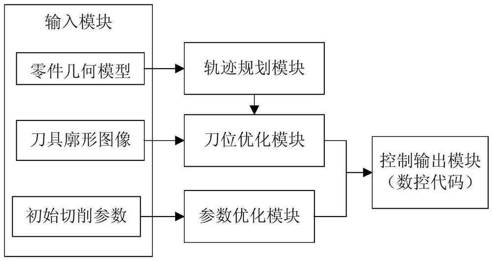
[0066] In this embodiment, a high-speed precision machining system for complex curved surface machining, such as figure 1 As shown, it includes input module, trajectory planning module, tool position optimization module, parameter optimization module, and control output module;

[0067] The input module is used to input the geometric model of the processed part, the tool profile image and the initial cutting parameters, and the output of the input module is respectively connected with the input of the trajectory planning module, the input of the tool position optimization module, and the input of the parameter optimization module connected; the cutting parameters include ...


PUM


Abstract

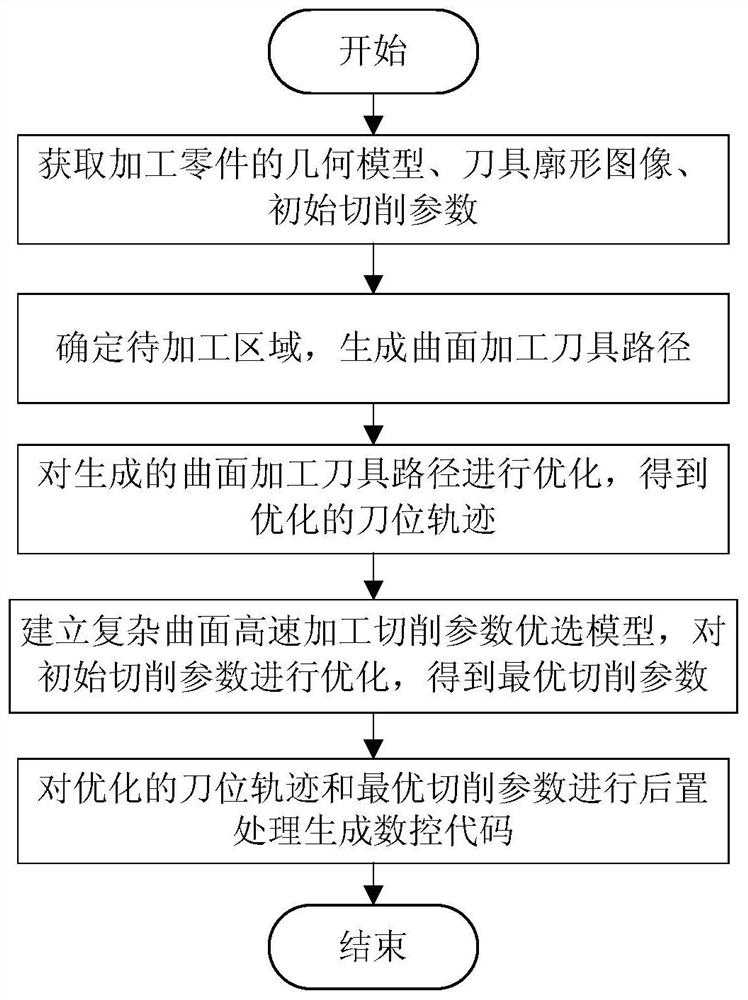
The invention provides a high-speed precision machining method for machining complex curved surfaces, and relates to the technical field of advanced manufacturing technology and equipment. The system and method first obtain the geometric model of the processed part, the tool profile image, and the initial cutting parameters; according to the characteristics of the surface to be processed, the surface processing tool path is generated, and the generated surface processing tool path is optimized to obtain the final optimized tool position Trajectory; use the double neural network optimization algorithm of complex curved surface cutting parameters to optimize the cutting time, energy consumption and surface roughness of the processed parts, establish a complex curved surface high-speed machining cutting parameter optimization model, optimize the initial cutting parameters, and obtain the optimal cutting Parameters; perform post-processing on the optimized tool path and optimized cutting parameters to generate NC codes. The method of the invention realizes the overall coordinated optimization of high-speed machining of complex curved surfaces, and improves the machining efficiency and precision of complex curved surfaces.

Description

technical field [0001] The invention relates to the technical field of advanced manufacturing technology and equipment, in particular to a high-speed precision machining method for complex curved surface machining. Background technique [0002] With the emergence of high-speed, high-precision CNC machining centers and the manufacturing accuracy of complex mechanical products approaching the limit state, almost stringent requirements have been put forward for the motion and geometric planning methods of CNC machining. High-speed, high-precision motion generation and control Technology has become the core technology for high-speed, high-precision and efficient processing of high-performance mechanical products. The current NC machining planning for complex curved surfaces is mostly selected by the operator or craftsman based on experience, given the process parameters and machine tool motion parameters, and the machining path planning is usually completed by UG or Pro / E system...

Claims


Application Information

Patent Timeline
Patent Type & Authority Patents(China)
IPC IPC(8): G05B19/19
CPCG05B19/19G05B2219/35524
Inventor 赵萍董威何亮韩迷慧王东生孙英鹏卜洪洋
Owner LIAONING PROVINCIAL COLLEGE OF COMM
Learn More