
Wire electric discharge machine having corner shape correcting function

a technology of wire electric discharge machine and corner shape, which is applied in the direction of machine control, process control, instruments, etc., can solve the problems of deteriorating excessive machined workpieces of the wire electrode b>4/b>, and long machining time, so as to improve the shape accuracy of the corner section

Active Publication Date: 2019-06-04
FANUC LTD
View PDF30 Cites 0 Cited by
  • Summary
  • Abstract
  • Description
  • Claims
  • Application Information

AI Technical Summary

Benefits of technology

The machine effectively minimizes shape errors on both surfaces by correcting wire guide positions, enhancing machining accuracy without increasing machining time, thus achieving improved corner section precision.

Problems solved by technology

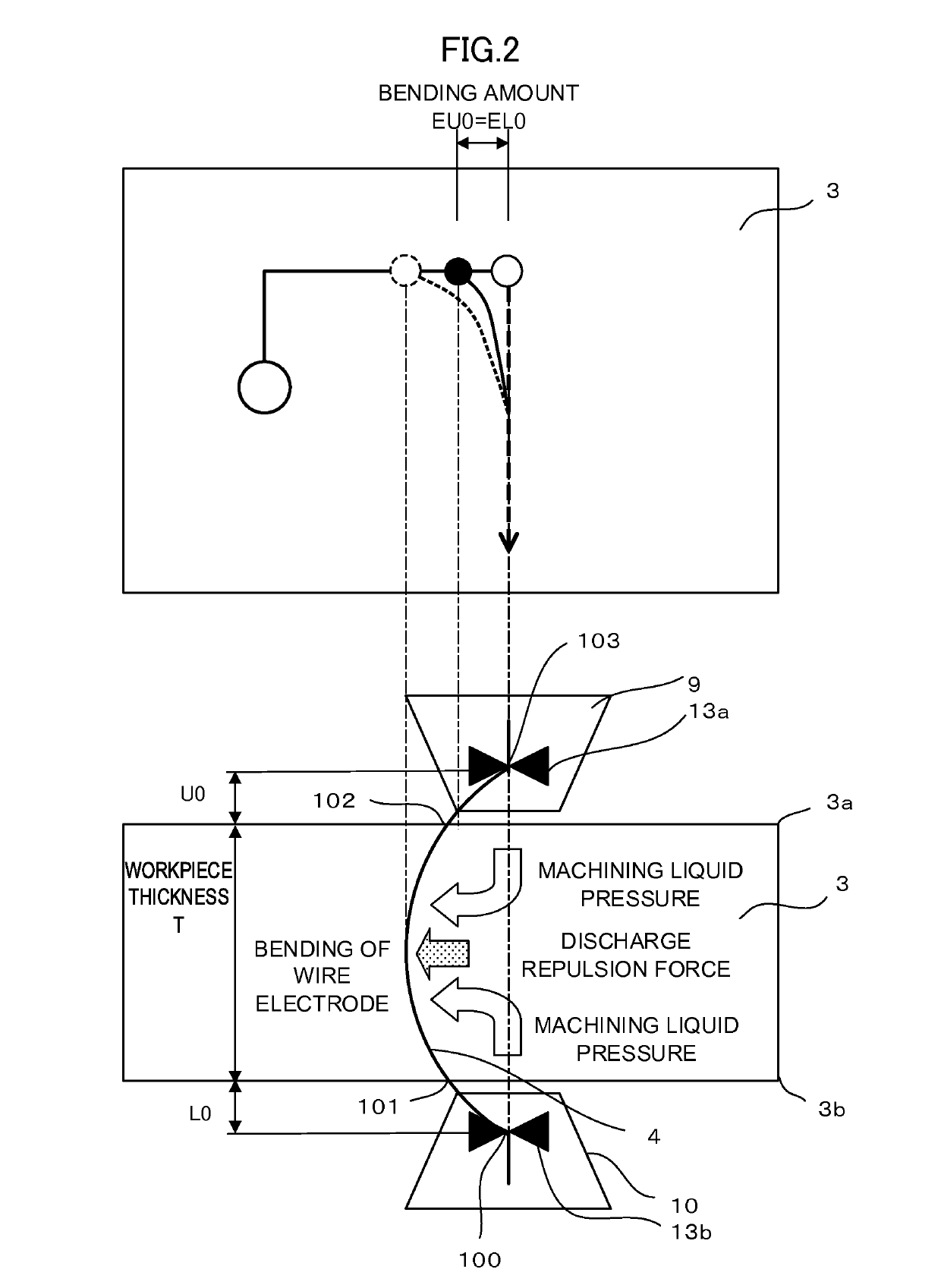
However, large influence of the bending of the wire electrode appears in machining of a corner section machined at a predetermined angle set in a machining program and greatly deteriorates shape accuracy of the corner section.
As a result, the wire electrode 4 excessively machines the workpiece 3.
Therefore, there is a disadvantage that a machining time is long.
However, machining by the wire electric discharge machine is not always machining in which the guide sections and the nozzles are closely attached to the upper and lower surfaces of the workpiece.
However, on the workpiece upper surface, bending due to vibration of the wire electrode further increases.
Therefore, correction of the workpiece upper surface is not correctly performed even if the shape of the workpiece lower surface is corrected.
Consequently, improvement of shape accuracy of a machining shape of the workpiece is insufficient.

Method used


Image

  • Wire electric discharge machine having corner shape correcting function
  • Wire electric discharge machine having corner shape correcting function
  • Wire electric discharge machine having corner shape correcting function

Examples


Embodiment Construction

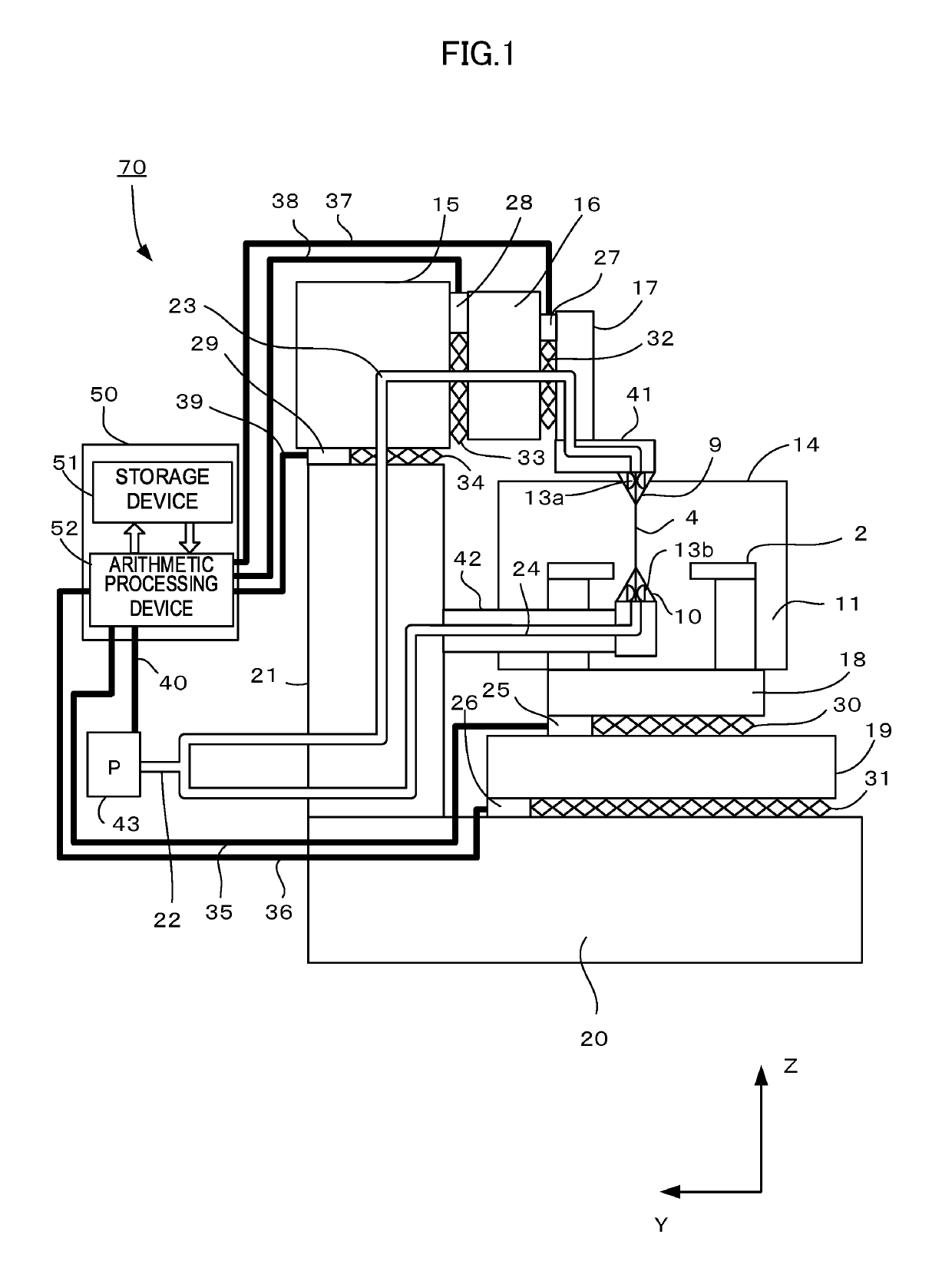
[0048]FIG. 1 is a schematic configuration diagram of a wire electric discharge machine.

[0049]A wire electric discharge machine 70 generates electric discharge between a wire electrode 4 and workpiece 3, which is a workpiece, placed on a table 2 to perform machining of the workpiece 3. The wire electric discharge machine 70 includes, on a base 20, an X-axis saddle 19 that moves in an X-axis direction with a ball screw 31 driven by an X-axis motor 26. The wire electric discharge machine 70 includes, on the X-axis saddle 19, a Y-axis saddle 18 that moves in a Y-axis direction with a ball screw 30 driven by a Y-axis motor 25. A machining tank 14 including the table 2, on which the workpiece 3 is placed, on the inside is fixed on the Y-axis saddle 18.

[0050]A column 21 is provided perpendicularly to the base 20. A lower arm 42 is horizontally attached to a side surface section of the column 21. A lower nozzle 10 and a lower wire guide 13b are attached to the distal end of the lower arm 42...


PUM

PropertyMeasurementUnit
thicknessaaaaaaaaaa
thicknessaaaaaaaaaa
thicknessaaaaaaaaaa

Abstract

A wire electric discharge machine has a function of performing correction of corner shapes independently on an upper surface and a lower surface of workpiece. On the basis of the positions of upper and lower wire guides and the position and the thickness of the workpiece, the wire electric discharge machine calculates, on the upper and lower surfaces of the workpiece, a shape correction amount in a state in which there is a space between the upper nozzle and the upper surface of the workpiece and also in which there is a space between the lower nozzle and the lower surface of the workpiece, from a correction amount at the time when nozzles of the upper and lower wire guides are closely attached to the upper and lower surfaces of the workpiece. The wire electric discharge machine performs shape correction according to the calculated shape correction amount.

Description

RELATED APPLICATIONS[0001]The present application claims priority to Japanese Application Number 2014-234581, filed Nov. 19, 2014, and Japanese Application Number 2015-197936 filed on Oct. 5, 2015, the disclosures of which are hereby incorporated by reference herein in their entirety.BACKGROUND OF THE INVENTION[0002]1. Field of the Invention[0003]The present invention relates to a wire electric discharge machine and, more particularly, to a wire electric discharge machine capable of reducing a shape error due to bending of a wire electrode on the upper and lower surfaces of workpiece and attaining improvement in shape accuracy of the workpiece by correcting, independently in an upper guide section and a lower guide section, the positions of upper and lower wire guides in a relative movement command of a wire guide with respect to the workpiece commanded by a machining program.[0004]2. Description of the Related Art[0005]In wire electric discharge machining, it is known that a wire e...

Claims


Application Information

Patent Timeline
Patent Type & Authority Patents(United States)
IPC IPC(8): B23H7/06B23H1/02B23H7/26B23H7/08B23H7/20
CPCB23H7/065B23H1/02B23H7/20B23H7/26B23H7/08G05B2219/45043
Inventor HASEGAWA, YASUO
Owner FANUC LTD
Learn More