Assembled paying-off pulley and paying-off tackle

A pay-off pulley, assembled technology, applied in the installation of cables, overhead lines/cable equipment, electrical components, etc., can solve the problems of high transportation costs, difficult removal, and heavy workload, saving engineering costs, reducing Manufacturing cost and the effect of improving ergonomics

Active Publication Date: 2013-01-09
CHINA ELECTRIC POWER RES INST +1
View PDF10 Cites 7 Cited by
  • Summary
  • Abstract
  • Description
  • Claims
  • Application Information

AI Technical Summary

Problems solved by technology

Existing pay-off blocks all use integral pulleys (such as figure 1 shown), such as the invention patent with the patent number 200810105399.4, which consists of a sliding hub, spokes and wheel grooves. This pay-off block has the following disadvantages: 1. After the rubber lining is partially damaged, it is necessary to remove the original lining and hang it again Glue, because the rubber is bonded while hot pressing, it is very difficult to remove, and it is usually done by machining
Sometimes it is forced to directly replace the pulley; 2. Due to the large size of the wheel body, two sets of large-scale special equipment are required, resulting in waste of resources; 3. The user unit cannot solve the problem of re-hanging the glue by itself. Large, high transportation costs; 4. Since the bearing is installed by heat or pressure, it is difficult to disassemble and assemble during maintenance

Method used


Image

  • Assembled paying-off pulley and paying-off tackle
  • Assembled paying-off pulley and paying-off tackle
  • Assembled paying-off pulley and paying-off tackle

Examples


Embodiment Construction

[0032] The present invention will be further described in detail below in conjunction with the accompanying drawings and specific embodiments.

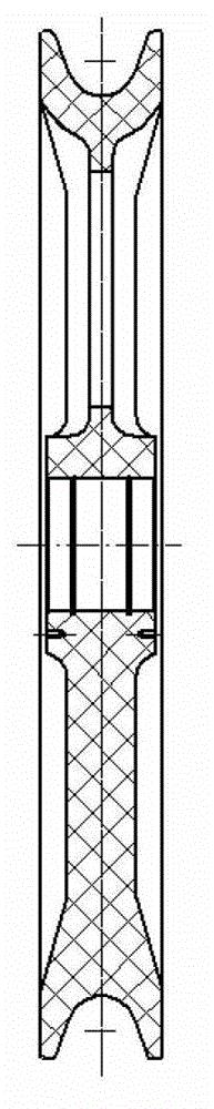
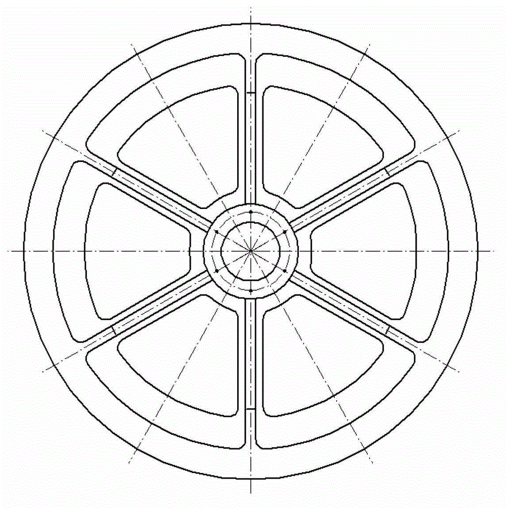
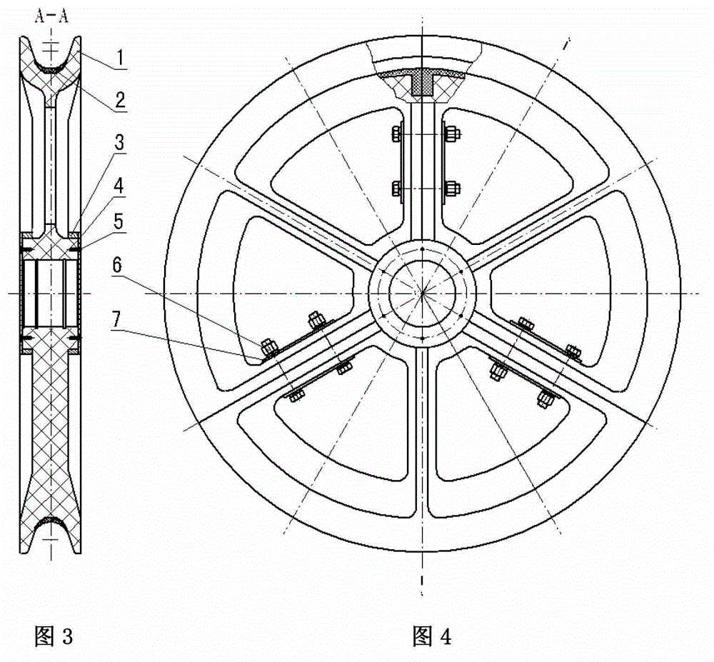
[0033] Such as image 3 , Figure 4 and Figure 6 In the shown embodiment, the pay-off pulley provided by the present invention is mainly composed of three identical pulley blocks 1 through threaded connection, and the rubber lining 2 is sleeved on the pulley body formed by the threaded connection of the pulley blocks 1, and The rubber lining 2 is in interference fit with the pulley body, and the fit tolerance is less than -1mm. The pulley block 1 is a fan-shaped frame, and the central angle of each pulley block 1 is the same as 120°, and three pulley blocks 1 are assembled into a 360° pulley body; the pulley body can also be composed of 2 pulley blocks with a central angle of 180° It consists of 1 or 4 pulley blocks 1 with a central angle of 90°. The joint surface between the pulley blocks 1 is smooth, and the diameter concentrici...


PUM


Abstract

The invention discloses an assembled paying-off pulley. The assembled paying-off pulley comprises a pulley body and a rubber liner arranged on the pulley body, wherein the pulley body mainly comprises at least two sliding pulley blocks; adjacent sliding blocks are connected with each other through threads; the rubber liner is in interference fit with a pulley groove of the pulley body; and moreover, the contact surface between the pulley groove and the rubber liner is a combination surface with roughness. According to the assembled paying-off pulley, the rubber liner is in interference fit with the pulley body, and the rubber liner is sleeved on the pulley body instead of being formed by hot-pressing and bonding, so that the rubber liner is convenient to replace after being damaged, and can be replaced manually without using related equipment; and troubles of replacing by entrusting a specialized manufacturer are avoided, and furthermore, the replacement of the pulley can be finished at a construction site.

Description

technical field [0001] The invention relates to a pay-off pulley for a power transmission line, and the invention also relates to a pay-off pulley provided with said wire pay-off pulley. Background technique [0002] The pay-off pulley is one of the main components of the pay-off block. The pay-off block mainly includes wire pay-off pulley, traction wire rope pulley and load-bearing frame, etc. The pay-off block is the most used tool in the wire erection construction, and hundreds or hundreds of sets are used at the same time. During the tension stringing process of the transmission line, the wire is drawn and unwrapped by the tractor through the pay-off block through the tension machine, that is, the tractor is used as the traction power, and the tension machine provides adjustable resistance torque to form a traction rope, a walking board, and a connector. The connection system with the wires, the deployment of the wires is completed through multiple pay-off tackles, and...

Claims


Application Information

Patent Timeline
Patent Type & Authority Applications(China)
IPC IPC(8): H02G1/02H02G11/00
Inventor 裘雅萍
Owner CHINA ELECTRIC POWER RES INST
Why Eureka
Try Eureka