Stator core and manufacturing method thereof

A stator core and circle center technology, which is applied in the field of magnetic circuit components, can solve the problems of the performance degradation of the amorphous alloy stator core and the hidden dangers of structural stability, and achieve the effect of avoiding a large drop and avoiding interlayer cracking

Inactive Publication Date: 2013-01-09
ADVANCED TECHNOLOGY & MATERIALS CO LTD
View PDF9 Cites 21 Cited by
  • Summary
  • Abstract
  • Description
  • Claims
  • Application Information

AI Technical Summary

Problems solved by technology

The iron core or internal magnetic circuit made by the above method contains a large number of air gaps, or there are hidden dangers in the structural stability, and the thermal curing treatment of the resin will lead to a significant decrease in the performance of the amorphous alloy stator core.

Method used


Image

  • Stator core and manufacturing method thereof
  • Stator core and manufacturing method thereof
  • Stator core and manufacturing method thereof

Examples


Embodiment Construction

[0040] The stator core of the present invention and its manufacturing method will be described in detail below with reference to the accompanying drawings.

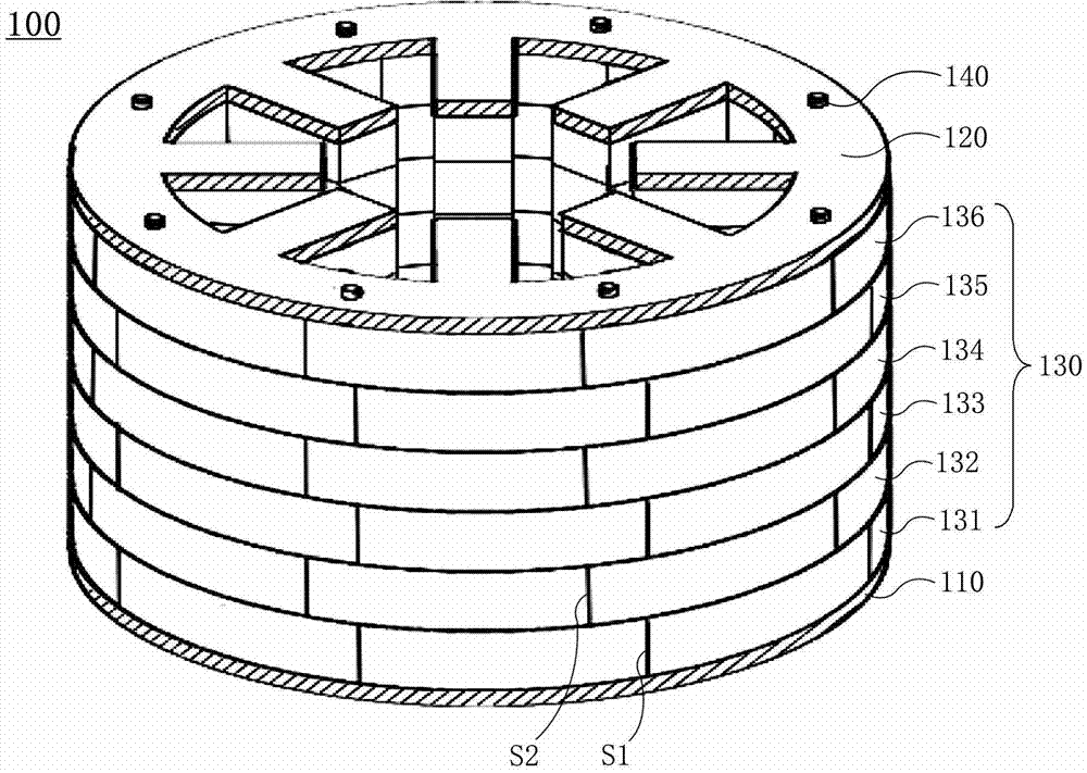
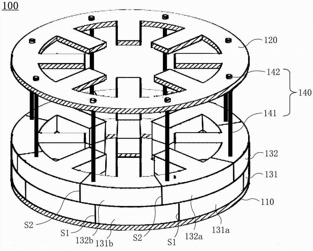
[0041] figure 1 is a perspective view of the stator core of the present invention, figure 2 is an exploded perspective view of the stator core of the present invention. refer to figure 1 and figure 2 , the stator core 100 of the present invention includes a lower end plate 110, an upper end plate 120, a plurality of stacks 130 arranged between the lower end plate 110 and the upper end plate 120, and the lower end plate 110, the upper end plate 120 and the plurality of stacks 130 are fixed A plurality of connecting members 140 together. The stacks 130 include a first stack 131 , a second stack 132 , a third stack 133 , a fourth stack 134 , a fifth stack 135 and a sixth stack 136 stacked on the lower end plate 110 in sequence. . Although figure 1 It is shown that the stacks 130 include six stacks, but the present i...


PUM


Abstract

The invention provides a stator core and a manufacturing method thereof. The stator core comprises a lower end plate, an upper end plate, a plurality of laminated bodies and a plurality of connection members, wherein the laminated bodies are laminated between the lower end plate and the upper end plate; the connection members are penetrated through the laminated bodies and are connected with the lower end plate and the upper end plate; each laminated body comprises a plurality of laminated body units which are sequentially arranged in the circumferential direction and form a circumference; each laminated body unit comprises a yoke part and an inner tooth; the yoke part is an arc-shaped flat piece or plate; the inner tooth is a flat piece or plate and extends from the yoke part to the circle center of the yoke part; at least one of the yoke part and the inner tooth comprises a hole; adjacent laminated body units among the multiple laminated body units of each laminated body form joint seams; each connection member comprises a rod; the rod is penetrated through the hole of the laminated body unit; the lower end of the rod is fixed to the lower end plate, and the upper end of the rod is fixed to the upper end plate; the yoke parts of the multiple laminated bodies overlap along the direction of the rod; the inner teeth of the multiple laminated bodies overlap along the direction of the rod; and the multiple joint seams of the adjacent laminated bodies among the multiple laminated bodies do not overlap.

Description

technical field [0001] The present invention relates to magnetic circuit components of motors or generators, in particular to a stator core and a manufacturing method thereof, more specifically to a high-performance amorphous, microcrystalline and nanocrystalline alloy stator core for a radial field motor and its Manufacturing method. Background technique [0002] In my country, the power consumption of electric motors (hereinafter referred to as motors) is about 50% of the total electricity consumption in the country and exceeds 70% of industrial electricity consumption. Therefore, improving the efficiency of motors has important social benefits and economic value. Amorphous, microcrystalline and nanocrystalline alloy materials have excellent soft magnetic properties such as high magnetic permeability and low loss. After being applied to motors, they can greatly reduce the iron loss of the motor and improve the efficiency of the motor. [0003] The loss of the motor is mai...

Claims


Application Information

Patent Timeline
Patent Type & Authority Applications(China)
IPC IPC(8): H02K1/14H02K15/02
Inventor 周少雄张广强王立军李山红
Owner ADVANCED TECHNOLOGY & MATERIALS CO LTD
Why Eureka
Try Eureka