Helix machining path for numerical-control small tool polishing

A processing path and helix technology, which is applied in the field of helical processing path for CNC small tool polishing, to achieve the effects of improving accuracy, reducing ripple error and wide adaptability

Inactive Publication Date: 2013-01-16
TSINGHUA UNIV
View PDF8 Cites 19 Cited by
  • Summary
  • Abstract
  • Description
  • Claims
  • Application Information

AI Technical Summary

Problems solved by technology

[0015] The purpose of the present invention is to provide a helical machining path for polishing small numerical control tools, so as to solve the problem that the existing path easily leads to two kinds of intermediate frequency errors, concentric circle error and radial wave error, in order to reduce the small The intermediate frequency error of tool polishing technology provides a more optimal processing path

Method used


Image

  • Helix machining path for numerical-control small tool polishing
  • Helix machining path for numerical-control small tool polishing
  • Helix machining path for numerical-control small tool polishing

Examples


Embodiment Construction

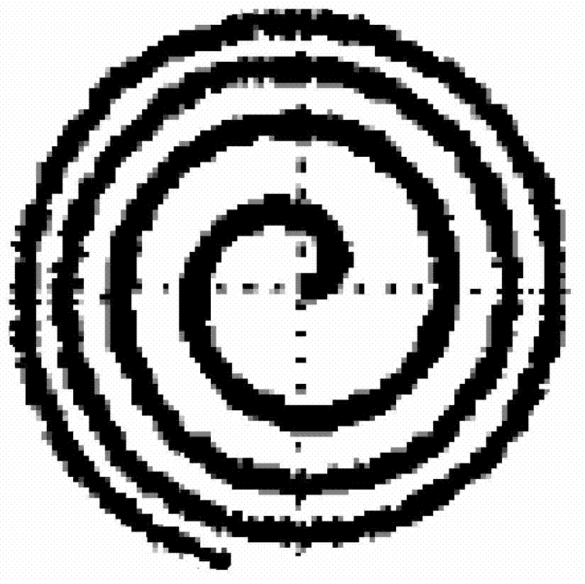
[0028] Figure 4 It is the spiral processing path of the present invention. The spiral processing path is composed of n discrete points in a polar coordinate system θ-r with θ as the polar angle and r as the radius coordinate value, namely {P 1 ,P 2 ,P 3 …P k ,P k+1 …P n }, and are generated from the center outwards, and the distance to the center becomes larger; the starting point of the spiral processing path P 1 Located at the pole of the polar coordinate system θ-r, point P 1 The polar coordinates are (θ 1 ,r 1 )=(0,0); It is characterized in that the spiral processing path follows the following geometric relationship:

[0029] k=1,2,...n-1 n,k are all positive integers,

[0030] θ k+1 =θ k +Δθ k k=1,2,...n-1 n,k are all positive integers,

[0031] Δ θ k = arccos ( ( r k ) 2 + ( r k + 1 ) 2 - Δ l 2 2 r k · r k + 1 ) k ≥ 2 Δ θ k = Δ θ 1 k = 1 ...


PUM


Abstract

The invention relates to a helix machining path for numerical-control small tool polishing, belongs to the technical field of optical machining, and aims to solve the problem that the existing helix polishing path easily causes large medium-frequency error. A novel discrete helix machining path no longer maintaining constant angle increment and radius increment in generation process is constructed by introducing weight factors, the helix machining path is composed of n discrete points under a polar coordinate system with a polar angle theta and a radius coordinate value r and is generated from the center to outside sequentially, distance from the helix machining path to the center is largened sequentially, and accordingly two medium-frequency errors, namely concentric-circle-shaped corrugated error and radial corrugated error related to surface shape of a workpiece, can be reduced, and precision of the optical workpiece is further increased.

Description

Technical field [0001] The invention belongs to the technical field of optical processing, and particularly relates to a spiral processing path used for polishing of numerically controlled small tools. Background technique [0002] As people have higher and higher requirements for the accuracy of optical systems, optical workpieces have clearly shown a trend toward large-scale, high-precision, and aspherical surfaces. Polishing, as the final process of optical workpiece shaping, is crucial to the manufacture of modern optical workpieces. [0003] However, the traditional optical workpiece polishing technology uses a polishing tool larger than the workpiece or approximately the same size, which is particularly inconvenient when polishing large-scale workpieces. In the traditional polishing method, the surface shape (face shape) error convergence of the workpiece is slow. It is even difficult to converge to the allowable range of a high-precision optical system; in the process of pr...

Claims


Application Information

Patent Timeline
Patent Type & Authority Applications(China)
IPC IPC(8): B24B29/02
Inventor 张云王于岳祝徐兴冯之敬
Owner TSINGHUA UNIV
Why Eureka
Try Eureka