Virtual wall system

A virtual wall and ultraviolet technology, applied in the field of virtual wall system, can solve the problem of high energy consumption

Inactive Publication Date: 2013-01-16
LUMIPLUS TECH SUZHOU CO LTD
View PDF6 Cites 13 Cited by
  • Summary
  • Abstract
  • Description
  • Claims
  • Application Information

AI Technical Summary

Problems solved by technology

[0004] Based on this, it is necessary to provide a virtual wall system with low energy consumption to solve the problem of high energy consumption of traditional virtual wall technology

Method used


Image

  • Virtual wall system
  • Virtual wall system
  • Virtual wall system

Examples


Embodiment Construction

[0020] In order to make the objects, features and advantages of the present invention more comprehensible, specific implementations of the present invention will be described in detail below in conjunction with the accompanying drawings.

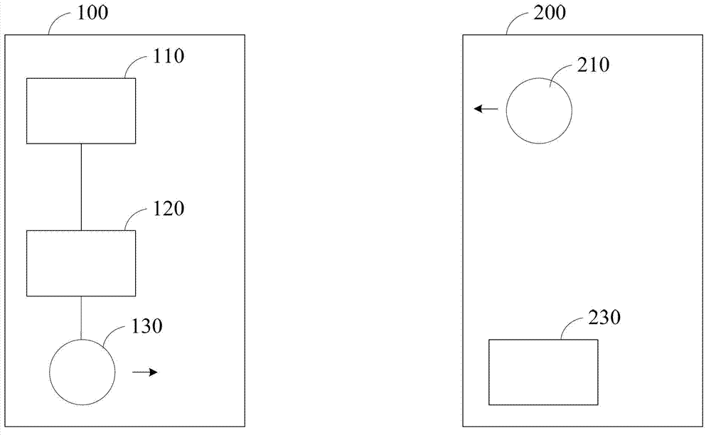
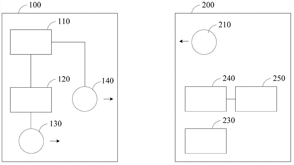
[0021] figure 1 It is a schematic structural diagram of a virtual wall system in an embodiment, and the virtual wall system includes a self-propelled device 200 and at least one fixing device 100 . Wherein, the self-propelled device 200 includes a first ultraviolet emitting device 210 and an infrared receiving device 230 ; the fixing device 100 includes a first ultraviolet receiving device 110 , a switch module 120 and an infrared emitting device 130 .

[0022] The infrared emitting device 130 is usually in an off state, while the first ultraviolet emitting device 210 is in a normally on state. When the first ultraviolet receiving device 110 receives the ultraviolet light emitted by the first ultraviolet emitting device 210 , the infrared e...


PUM


Abstract

The invention relates to a virtual wall system, which comprises a self-walking device and at least one fixed device, wherein the self-walking device comprises an infrared receiving device and also comprises a first ultraviolet emitting device; the fixed device comprises an infrared emitting device and also comprises a first ultraviolet receiving device and a switch module which are mutually connected; and when the first ultraviolet receiving device receives ultraviolet rays emitted by the first ultraviolet emitting device, the switch module turns on the infrared emitting device. By the utilization of the characteristics that the ultraviolet rays have low energy consumption and weak penetrability compared with the infrared rays, the infrared emitting device of the self-walking device is in a turn-on state only near the boundary of a virtual wall. The infrared emitting device does not need to be in a continuous turn-on state, so that electric energy consumption can be saved compared with the traditional technology.

Description

technical field [0001] The invention relates to the technology of using electromagnetic waves for navigation, in particular to a virtual wall system. Background technique [0002] The traditional virtual wall technology is to install an infrared receiving device on a self-propelled device (such as a self-propelled robot, a self-propelled vehicle, a self-propelled vacuum cleaner, etc.), and install an infrared emitting device for directional emission on at least one fixed device. When the self-propelled device travels to the range of the infrared rays, the operation of the self-propelled device stops or turns to form a virtual limited space. [0003] However, since the infrared emitting and receiving device must be turned on continuously, the energy consumption is high and it is not environmentally friendly. Contents of the invention [0004] Based on this, it is necessary to provide a virtual wall system with low energy consumption to solve the problem of high energy cons...

Claims


Application Information

Patent Timeline
Patent Type & Authority Applications(China)
IPC IPC(8): G05D1/02
Inventor 汪有志
Owner LUMIPLUS TECH SUZHOU CO LTD
Why Eureka
Try Eureka