

Grid driving circuit and driving method thereof and display device
A gate drive circuit and gate technology, applied to static indicators, instruments, etc., can solve the problems of difficult to apply small-sized panels, difficult to meet actual design needs, and large wiring space, so as to reduce the number and Wiring space, to achieve the effect of narrow frame
- Summary
- Abstract
- Description
- Claims
- Application Information
AI Technical Summary
Problems solved by technology
Method used
Image

Examples
Embodiment 1
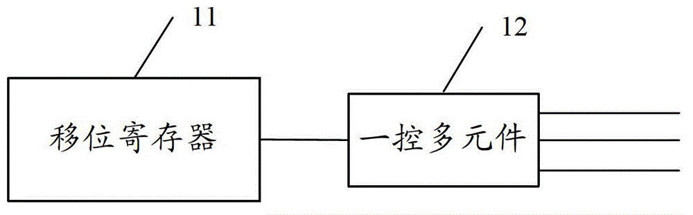
[0071] An embodiment of the present invention provides a gate drive circuit, such as image 3 As shown, including: shift register 11, also includes:
[0072] The one-control-multiple unit 12 is configured to receive the first pulse signal output by the shift register 11 and output a plurality of second pulse signals, and the plurality of second pulse signals are used to drive a plurality of gate lines.
[0073] In this embodiment, by adding a one-control multi-unit to the shift register, a pulse signal output by a shift register is converted into multiple pulse signal outputs, which are respectively used to drive multiple gate lines, so that a shift register can Simultaneously controlling multiple gate lines greatly reduces the number of shift registers, thereby reducing the wiring space and facilitating the realization of a narrow panel frame.
[0074] A multi-control unit 12 is connected to the output terminal of the shift register 11, and is used to divide the received fir...
Embodiment 2
[0084] A gate drive circuit of the present invention, another specific implementation example is as follows:
[0085] Such as Figure 5 and Figure 6 As shown, the gate drive circuit includes: a shift register 11 and a multi-control unit 12 connected to the output end of the shift register 11, and the multi-control unit 12 includes:
[0086] The source of the first thin film transistor T1 is connected to the output terminal of the shift register 11, the drain is connected to the odd-numbered gate line (OUT-O) of the two adjacent gate lines, and the gate receives the first control signal V1;
[0087] The source of the second thin film transistor T2 is also connected to the output terminal of the shift register 11, the drain is connected to the even-numbered gate line (OUT-E) of the two adjacent gate lines, and the gate receives the second control signal V2 ;
[0088] The third thin film transistor T3, the source of which is input with the ground voltage signal Vss, the drain...
Embodiment 3
[0104] A gate drive circuit of the present invention, such as Figure 9 As shown, another specific implementation example is as follows:
[0105] The gate drive circuit includes: a shift register 11 and a multi-control unit 12 connected to the output of the shift register 11. The difference is that the multi-control unit 12 includes:
[0106] The source of the seventh thin film transistor T7 is connected to the output terminal of the shift register 11, the drain is connected to the first (OUT_1) of the three adjacent gate lines, and the gate receives the third control signal V3;
[0107] The source of the eighth thin film transistor T8 is also connected to the output terminal of the shift register 11, the drain is connected to the second (OUT_2) of the three adjacent gate lines, and the gate receives the fourth control signal V4;
[0108] The source of the ninth thin film transistor T9 is also connected to the output terminal of the shift register 11, the drain is connected t...
PUM
 Abstract
Description
Claims
Application Information