Imaging device and imaging method

An image and medium technology, applied in printing devices, copying/marking methods, printing, etc., can solve the problems of inability to print high-quality images, increased gap between inkjet head and transfer pad, inaccurate ink drop landing, etc. problem, achieve the effect of shortening image forming time, suppressing color shift, and reducing cost

Active Publication Date: 2013-01-16
MIMAKI ENG
View PDF7 Cites 13 Cited by
  • Summary
  • Abstract
  • Description
  • Claims
  • Application Information

AI Technical Summary

Problems solved by technology

[0007] However, since the transfer pad is formed in a three-dimensional structure, the gap between the inkjet head and the transfer pad increases
Generally, for inkjet printers, if the gap between the inkjet head and the transfer pad increases, the landing of ink droplets is not accurate
Therefore, in the above-mentioned pad printing, there is a problem that the surface shape of the transfer pad is greatly restricted, and high-quality images cannot be printed.

Method used


Image

  • Imaging device and imaging method
  • Imaging device and imaging method
  • Imaging device and imaging method

Examples


no. 1 Embodiment approach ]

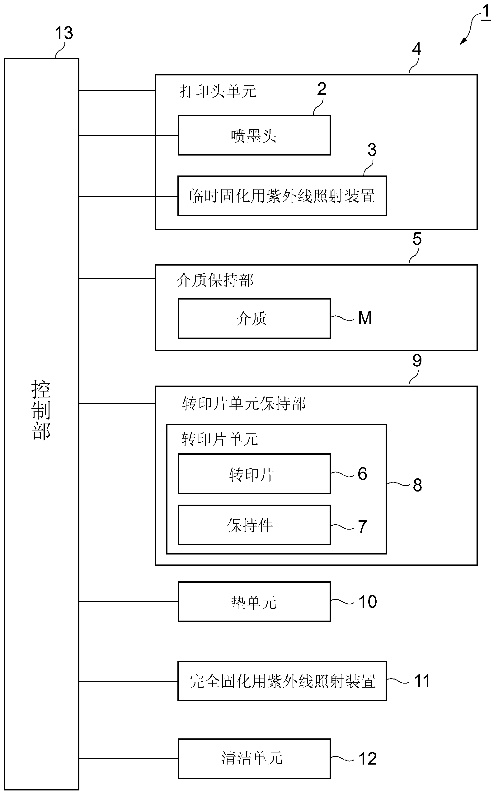
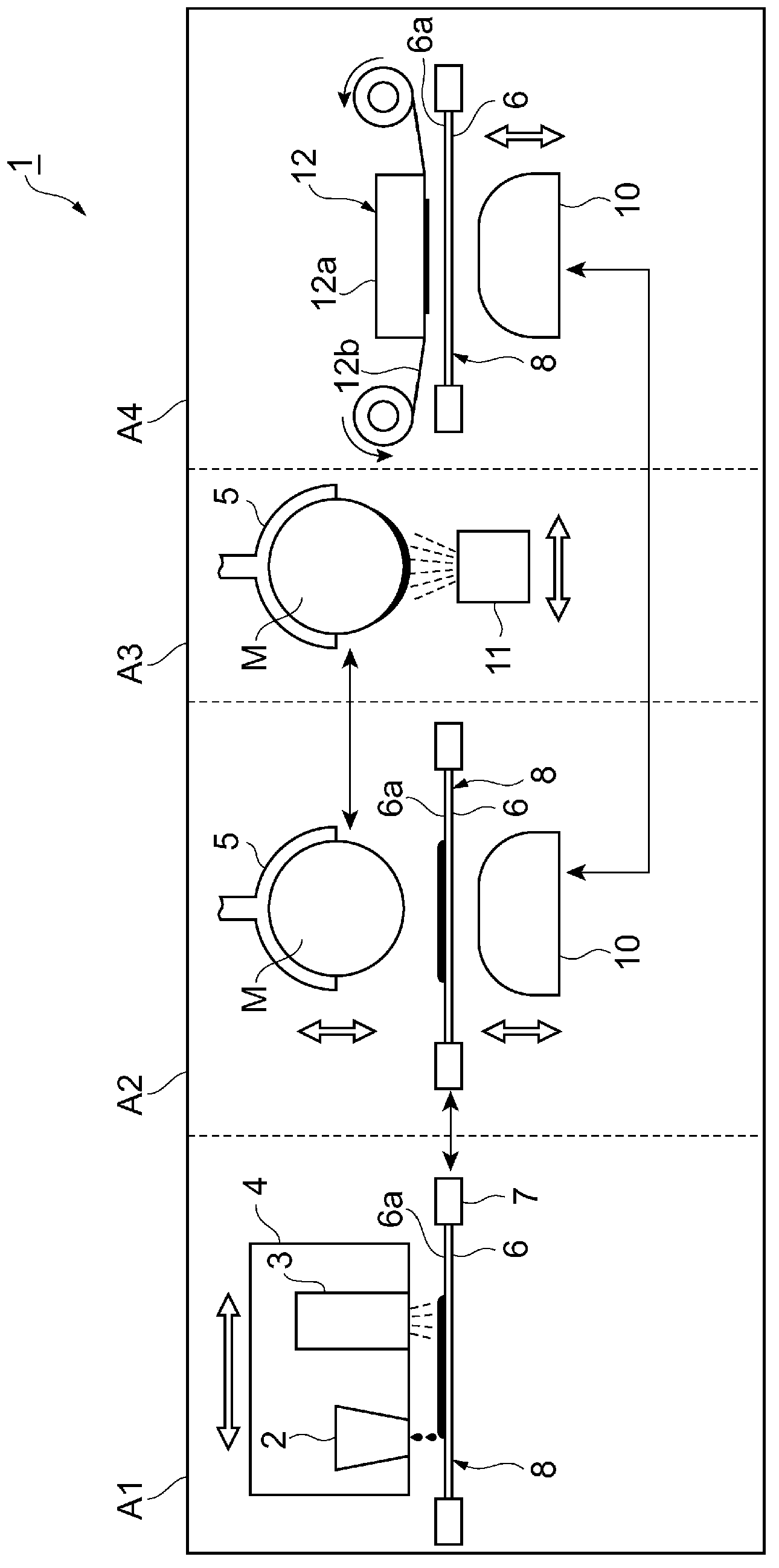
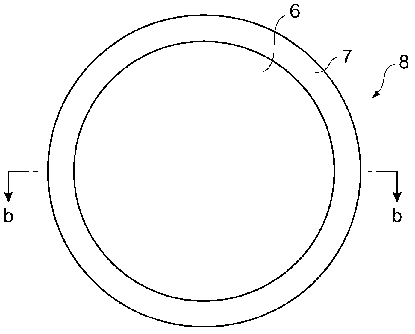
[0060] figure 1 It is a figure which shows the schematic structure of the inkjet printer of 1st Embodiment. figure 2 Yes figure 1 The schematic configuration diagram of the inkjet printer shown. Such as figure 1 with figure 2 As shown, the inkjet printer 1 includes: an inkjet head 2, an ultraviolet irradiation device 3 for temporary curing, a print head unit 4 for mounting the inkjet head 2 and an ultraviolet irradiation device 3 for temporary curing, and a medium for holding a medium M Holding part 5, transfer sheet unit holding part 9 for holding the transfer sheet unit 8 with the transfer sheet 6 mounted on the transfer sheet holder 7, pad unit 10, UV irradiation device 11 for complete curing, cleaning unit 12 and control unit 13.

[0061] The inkjet printer 1 is divided into four areas of a first area A1 to a fourth area A4. The first area A1 is an area where the ultraviolet curable ink is applied to the transfer sheet 6 and the ultraviolet curable ink applied to the trans...

no. 2 Embodiment approach ]

[0103] Picture 9 It is a figure which shows the schematic structure of the inkjet printer of 2nd Embodiment. Picture 10 Yes Picture 9 The schematic configuration diagram of the inkjet printer shown. Such as Picture 9 with Picture 10 As shown, the inkjet printer 21 is basically the same as the first embodiment, and includes an inkjet head 2, an ultraviolet irradiation device 3 for temporary curing, a print head unit 4 equipped with an inkjet head 2 and an ultraviolet irradiation device 3 for temporary curing, and The medium holding portion 5 for holding the medium M, the transfer sheet unit holding portion 9 for holding the transfer sheet unit 8 with the transfer sheet 6 mounted in the transfer sheet holder 7, the pad unit 10, the ultraviolet light for complete curing The irradiation device 11, the cleaning unit 12, and the control unit 13.

[0104] As in the first embodiment, the inkjet printer 21 is divided into a first area A1 to a fourth area A4. The print head unit 4 is...

no. 3 Embodiment approach

[0124] Figure 14 It is a figure which shows the schematic structure of the inkjet printer of 3rd Embodiment. Figure 15 Yes Figure 14 The schematic configuration diagram of the inkjet printer shown. Such as Figure 14 with Figure 15 As shown, the inkjet printer 31 is basically the same as the second embodiment, but is different in that it has a vacuum chamber 32 and a suction pump 33 instead of the pad unit 10. That is, the inkjet printer 31 includes an inkjet head 2, an ultraviolet irradiation device 3 for temporary curing, a print head unit 4 equipped with an inkjet head 2 and an ultraviolet irradiation device 3 for temporary curing, and a medium holding portion 5 for holding the medium M. , The transfer sheet unit holding portion 9 for holding the transfer sheet unit 8 with the transfer sheet 6 mounted in the transfer sheet holder 7, the vacuum chamber 32 connected to the suction pump 33, and the UV irradiation device 11 for complete curing , Cleaning unit 12 and control ...


PUM


Abstract

The present invention relates to an imaging device and an imaging method. The object of the present invention is to form, quickly and at low cost, a high-quality image on a medium formed with a curved surface. In order to achieve this object, the imaging device is equipped with: an ink-jet head (2); a pre-curing ultraviolet irradiation device (3); a head unit (4) in which is installed the ink-jet head (2) and the pre-curing ultraviolet irradiation device (3); a medium holding unit (5) that holds a medium (M); a transfer sheet unit holding unit (9) that holds a transfer sheet unit (8), in which a transfer sheet (6) is mounted to a transfer sheet holder (7); an elastic pad unit (10); a final curing ultraviolet irradiation device (11); a cleaning unit (12); and a control unit (13). The ink-jet head (2) applies ink to the transfer sheet (6) and the pad unit (10) pushes the transfer sheet (6) against the medium (M), thus providing a pressure transfer of the ink applied to the transfer sheet (6) to the medium (M).

Description

Technical field [0001] The present invention relates to an image forming apparatus and an image forming method for forming an image on a medium with a curved surface. Background technique [0002] Conventionally, as a method of forming an image on a medium, pad printing has been known. In this pad printing, an image is formed on the medium through the following steps: (1) Making a flat printing plate (gravure) with a printing pattern, (2) Putting ink into the printing pattern of the flat printing plate, (3) Press the flexible transfer pad from above the flat printing plate to transfer the ink in the printing pattern to the transfer pad. (4) Press the transfer pad to the medium to transfer the ink from the transfer pad to the medium. [0003] In addition, in recent years, a method of forming an image on a medium through the following steps has also been known: (1) using an inkjet printer to coat ink on a flat printing plate, (2) thickening the ink on the flat printing plate, (3) P...

Claims


Application Information

Patent Timeline
Patent Type & Authority Applications(China)
IPC IPC(8): B41J2/01B41M5/00
CPCB41M5/0256B41J11/002B41J2/0057B41J3/4073B41J11/00214B41F17/001B41M5/00B41J2/01
Inventor 大西胜
Owner MIMAKI ENG
Why Eureka
Try Eureka