

Conductive sliding film, member formed from conductive sliding film, and method for producing same
A technology of conductivity and components, which is applied in the direction of conductive materials dispersed in non-conductive inorganic materials, optical components, camera bodies, etc., can solve problems such as low reflectivity, development, and inability to ensure appearance quality, and achieve wear resistance High performance and good sliding properties
- Summary
- Abstract
- Description
- Claims
- Application Information
AI Technical Summary
Problems solved by technology
Method used
Image

Examples
Embodiment 1~8
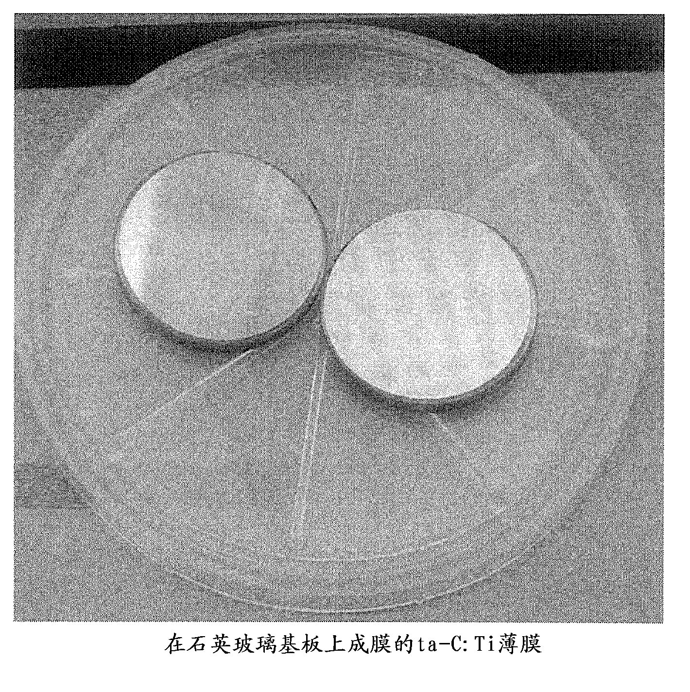
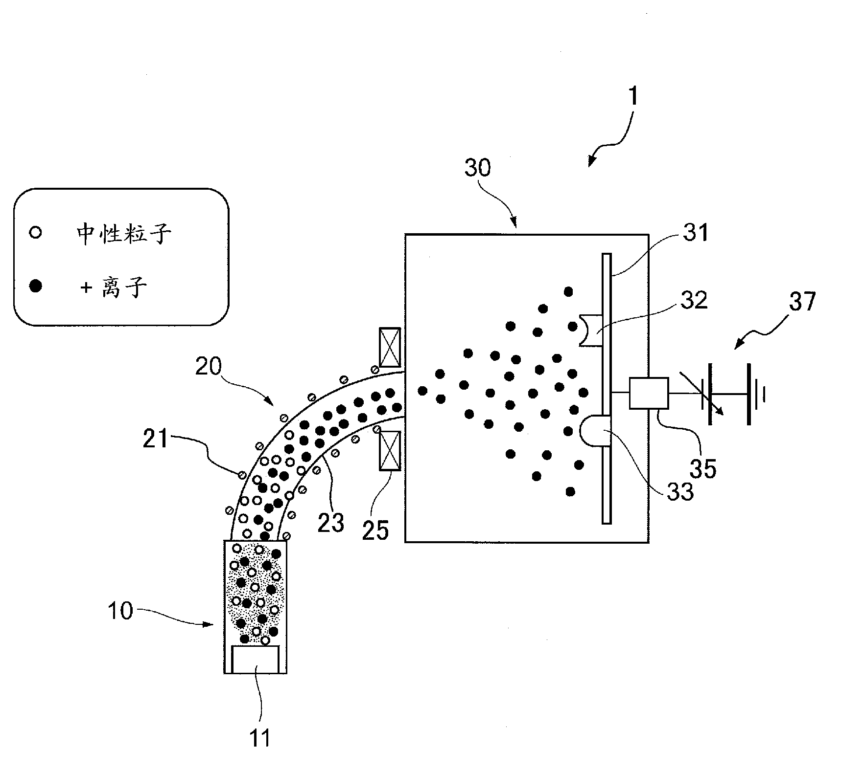
[0065] will use image 3 Examples of forming a conductive sliding film using the shown FCVA film forming apparatus 1 are shown below. In this example, a sintered graphite target containing Ti 2.15 [at%] was used as the target 11 containing metal elements, and a ta-C:Ti film (titanium-doped tetrahedral amorphous carbon film) was formed on the surface of the substrate. It should be noted that, as the sintered graphite target, a dehydrated graphite target was used. As will be described later, in order to separately evaluate the sheet resistivity, hardness, elastic modulus, film composition, friction coefficient, and wear resistance of the ta-C:Ti film, different substrates were used. The ta-C:Ti film was formed several times under different conditions. Specifically, in order to measure the sheet resistivity, the substrate used SiO 2 As for the glass substrate, a brass camera mounting part was used for evaluation of abrasion resistance, and a Si substrate was used for other cas...
Embodiment 9
[0070] Using a sintered graphite target containing Ti 2.15 [at%] that has not been dehydrated as the target 11 containing metal elements, the operating conditions of the FCVA film formation device 1 were changed to Figure 7 Except for the values shown, a film was formed in the same manner as in Example 1. A film with a film thickness of 365 [nm] was formed on the substrate at a film forming rate of 0.12 [nm / s].
[0071] The obtained film was analyzed for components constituting the film by the Rutherford backscattering method in the same manner as in Example 1. show the result in Figure 7 in the table. It should be noted that hydrogen could not be measured in the experiment for the film obtained in this example. In addition, the chemical composition in the depth direction of the film obtained in this example is shown in Figure 9 . exist Figure 9 In the coordinate diagram of , the horizontal axis is the depth from the film surface to the film thickness direction, an...
Embodiment 10~14
[0102] Set the operating condition of the FCVA unit to Figure 11 A ta-C:Ti film having a different Ti / C atomic ratio was formed in the same manner as in Example 1 except for the values shown in the table of . The Ti / C atomic ratio of the obtained film is shown in Figure 11 table. It should be noted that the atomic ratio (at %) in the Ti film was also recorded together. In addition, the volume resistivity, hardness, and dynamic friction coefficient of the obtained ta-C:Ti film were measured in the same manner as in Examples 1 to 9, and the results are shown in Figure 11 table. It should be noted that, as a reference, the physical properties of the films obtained in Examples 6 and 9 are also shown in Figure 11 in the table.
[0103] Loading and unloading durability test (evaluation of abrasion resistance)
[0104] Next, the performance of the sliding film as the mount of the camera was evaluated as follows. With the operating conditions of the FCVA devices in Exampl...
PUM
| Property | Measurement | Unit |
|---|---|---|
| Film thickness | aaaaa | aaaaa |
| Resistivity | aaaaa | aaaaa |
| Resistivity | aaaaa | aaaaa |
Abstract
Description
Claims
Application Information