
Numerical control cutting process of steel tube arch bridge pipe joint steel plate intersecting line

A steel pipe arch bridge and cutting process technology, which is applied in the direction of manufacturing tools, metal processing equipment, welding equipment, etc., can solve the problems of rough cutting surface, low cutting precision of pipe joint processing, and uneven curve transition, so as to reduce steel plate and The use of welding consumables, the production process is clear, and the effect of smooth curve transition

Active Publication Date: 2013-01-23
中铁宝桥(宝鸡)路桥建设有限公司
View PDF3 Cites 7 Cited by
  • Summary
  • Abstract
  • Description
  • Claims
  • Application Information

AI Technical Summary

Problems solved by technology

[0003] Design purpose: to avoid the deficiencies in the background technology, to provide a steel pipe arch bridge pipe section steel plate intersecting line numerical control cutting process, to solve the steel pipe arch bridge arch rib curve quality problem and pipe joint processing quality in the existing process, to improve work efficiency, and to provide Lay the foundation for improving the automation level of steel pipe arch bridge manufacturing
This application aims at the problems of low cutting precision, rough cutting surface, and unsmooth curve transition in the original process of "substituting bending instead of bending", and adopts a new process to cut the curve of the steel plate once, that is, to ensure the curve of the arch rib The requirements of intersecting lines can also meet the requirements of welding process grooves

Method used


Image

  • Numerical control cutting process of steel tube arch bridge pipe joint steel plate intersecting line
  • Numerical control cutting process of steel tube arch bridge pipe joint steel plate intersecting line

Examples


Embodiment 1

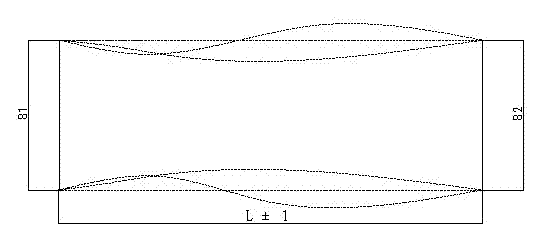
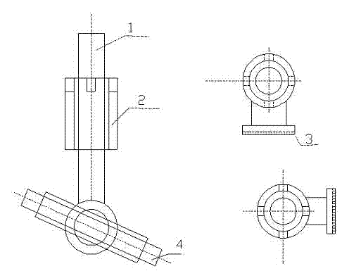
[0010] Embodiment 1: with reference to attached figure 1 and 2 . This process is a flame cutting method (a numerical control cutting method of intersecting line of steel pipe arch bridge tube section steel plate), including CNC flame cutting machine, that is, in WD-105 CNC flame cutting machine, (1) drawing steel pipe arch bridge by geometric method The curve diagram of the intersecting line of the pipe section steel plate is imported into the CNC flame cutting machine. (2) The CNC flame cutting machine is equipped with a corner device ( figure 2 Middle 2-steering device), this corner device can enable the CNC flame cutting machine to realize the turning and cutting in four directions, (3) carry out the curve cutting of the steel plate including the process groove required for welding, and then get the butt curve that can meet the requirements of the arch rib parts required.

[0011] 1. Determine method: Using the WD-105 CNC flame cutting machine, the curve diagram of th...


PUM


Abstract

The invention relates to a numerical control cutting process of a steel tube arch bridge pipe joint steel plate intersecting line. The numerical control cutting process comprises a numerical control flame cutting machine and comprises the following steps that (1) a curve graph of the steel tube arch bridge pipe joint steel plate intersecting line is drawn through a geometric method and led into the numerical control flame cutting machine; (2) an angle turning device is installed at the numerical control flame cutting machine, and steering cutting of the numerical control flame cutting machine in four directions can be realized through the angle turning device; and (3) curve cutting of a required process groove containing welding is carried out on a steel plate so as to obtain parts which meet a requirement on an arch rib abutting joint curve. The numerical control cutting process has the advantages that firstly, the steel plate is formed by adopting numerical control cutting for one time, so that a production organization is smoother; secondly, raw materials are saved; thirdly, operating time that a welder carries out the welding is reduced; fourthly, a welded joint is uniform and attractive in appearance, fifthly, an integrated one-time cutting process is adopted, a working procedure is less, a cutting surface and a line are smooth and continuous, and quality is high, sixthly, the quality of a cut curve and a flame cutting surface are both improved, seventhly, the operating time that the welder carries out the welding is reduced, eighthly, production efficiency is high, and ninthly, working efficiency is improved.

Description

technical field [0001] The invention belongs to the manufacture of bridge engineering steel structures, relates to a numerical control cutting process method for steel plates in the manufacturing process of arch rib pipe joints of steel pipe arch bridges, and belongs to the field of numerical control cutting. Background technique [0002] There are two commonly used methods for making the arch rib curve of steel pipe arch bridges: one is to make the straight pipe joints butt to the required length, and then deform it through hot simmering to meet the curve requirements. In the production, special equipment is required to use infrared ceramic electric heating technology The other is to divide the pipe joint into about two meters according to the design requirements and the corresponding process formulated by the manufacturing unit for steel plate blanking, circle making, cutting intersecting lines, assembly and other processes, so as to realize the requirements of the arch rib...

Claims


Application Information

Patent Timeline
IPC IPC(8): B23K7/00
Inventor 徐学年张西谋刘飞
Owner 中铁宝桥(宝鸡)路桥建设有限公司
Learn More