
Method for performing gear shifting control on automated gear shifting transmission

A technology of shifting transmission, shifting control, applied in the direction of transmission control, brake, brake type, etc., can solve the problem that the method cannot be transferred without problem.

Inactive Publication Date: 2013-01-23
ZF FRIEDRICHSHAFEN AG
View PDF2 Cites 3 Cited by
  • Summary
  • Abstract
  • Description
  • Claims
  • Application Information

AI Technical Summary

Problems solved by technology

However, based on the specific structure of the relevant powertrain system, the disclosed method cannot be transferred without problems to the currently assumed powertrain system

Method used


Image

  • Method for performing gear shifting control on automated gear shifting transmission
  • Method for performing gear shifting control on automated gear shifting transmission
  • Method for performing gear shifting control on automated gear shifting transmission

Examples


Embodiment Construction

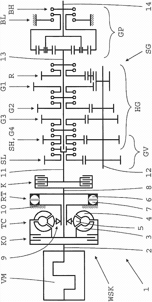
[0031] The basis on which the method according to the invention can be applied figure 2 The drivetrain 1 of the vehicle has a drive motor VM designed as an internal combustion engine with a drive shaft 2 (crankshaft), an automated shift transmission SG and a torque converter clutch WSK arranged between them. The torque converter clutch device WSK includes a torque converter TC with a turbine 3, a pump wheel 4 and a guide wheel 5; in addition includes a hydraulic retarder RT with a rotor 6 and a stator 7; Disengage the clutch K. The transmission shaft 2 of the drive motor VM is connected in a rotationally fixed manner to the pump wheel 4 of the torque converter TC. The turbine wheel 3 of the torque converter TC is connected in a rotationally fixed manner to the countershaft 8 and can be connected to the pump wheel 4 via the lock-up clutch K0 . The guide wheel 5 is connected to the housing part 10 for support via an overrunning clutch 9 . The rotor 6 of the retarder RT is con...


PUM


Abstract

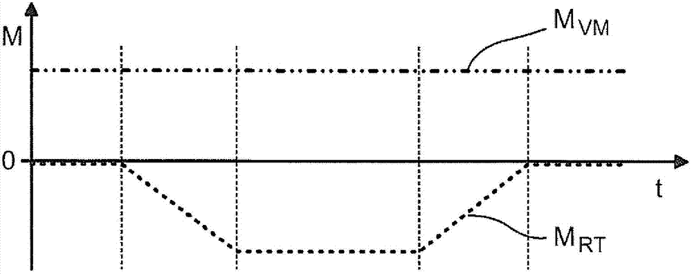
A method for performing gear shifting control on an automated gear shifting transmission. A torque conversion clutch device is placed in front of the transmission and includes: a hydraulic torque converter which has a pump impeller connected with a transmission shaft of a driving motor of an internal combustion engine configured for turbocharging, and a turbine connected with a middle shaft; a retarder of a rotor which is in transmission connection with the middle shaft; and a cut-off clutch configured to be an automated friction clutch and arranged between the middle shaft and an input shaft of the transmission, during traction and gear shafting, the input shaft of the transmission remains torque-free as far as possible through reduction of a load when gear shifting begins. To prevent weakening of motive force of the driving motor when traction and gear shifting finish and the load is established, the arrangement is that: in the circumstance of maintaining motor torque output by the driving motor, the reduction of the load on the input shaft is caused by absorbing correspondingly high retarding torque in the retarder, and the retarding torque absorbed from the retarder increases to above the motor torque of the driving motor at the beginning of traction and gear shifting, and reduces to zero when traction and gear shifting finish.

Description

technical field [0001] The invention relates to a method for the shift control of an automated gearshift transmission, in which a torque converter clutch (Wandlerschaltkupplung) transmission technology is preceded, the torque converter clutch comprising a hydraulic torque converter, It has a pump wheel connected to the drive shaft of the drive motor of a turbocharged internal combustion engine and a turbine wheel connected to the countershaft; it also includes a retarder with a rotor drive-connected to the countershaft; and a friction clutch designed as an automation and a separating clutch arranged between the countershaft and the input shaft of the shift transmission, wherein, during a traction shift (traction upshift or traction downshift), the input shaft of the shift transmission is dropped by the load that occurs at the start of the shift to keep it as moment-free as possible. Background technique [0002] Automated shift transmissions are being used more and more fre...

Claims


Application Information

Patent Timeline
Patent Type & Authority Applications(China)
IPC IPC(8): F16H61/02F16H63/40F16H61/682F16H61/14
CPCF16H63/502F16H2061/0414F16H61/682B60W10/196F16H61/02B60T1/087B60T10/02F16H63/40B60W30/19F16H61/14F16H61/04
Inventor 罗兰・梅尔弗洛里安・施奈德
Owner ZF FRIEDRICHSHAFEN AG
Learn More