Supercharge Your Innovation With Domain-Expert AI Agents!

Function safety monitoring development and demonstration system for major hazard source equipment

A functional safety and hazard source technology, applied in the direction of comprehensive factory control, comprehensive factory control, electrical program control, etc., can solve the problems of inability to warn and alarm, inability to realize emergency linkage, poor reliability, etc., and achieve the effect of avoiding personal accidents

Active Publication Date: 2014-09-17
CHINA ACAD OF SAFETY SCI & TECH +1
View PDF5 Cites 0 Cited by
  • Summary
  • Abstract
  • Description
  • Claims
  • Application Information

AI Technical Summary

Problems solved by technology

However, the installation of guardrails will greatly affect the observation and operation efficiency of the staff on the operation status of high-risk equipment, and will expand the space required to protect equipment and personnel safety, and the reliability is poor
For equipment such as manipulators in the machinery manufacturing industry, the use of guardrails may affect the normal operation of the equipment, and it is difficult to achieve effective, reliable and safe protection
[0004] In addition, there are some major hazard source equipment on site that draw a cordon around it, or draw a cordon on the ground to remind personnel of the dangerous area, but these two methods are too simple to attract sufficient attention from personnel, and It cannot effectively protect people who only have one part of their body entering the dangerous area, which is very dangerous
[0005] Third, the existing safety monitoring device has a single function. It only completes the on-site image monitoring of major hazard source equipment, and cannot realize early warning and alarm for personnel entering the dangerous area, let alone realize emergency linkage to stop the dangerous equipment in an emergency

Method used


Image

  • Function safety monitoring development and demonstration system for major hazard source equipment
  • Function safety monitoring development and demonstration system for major hazard source equipment

Examples


Embodiment Construction

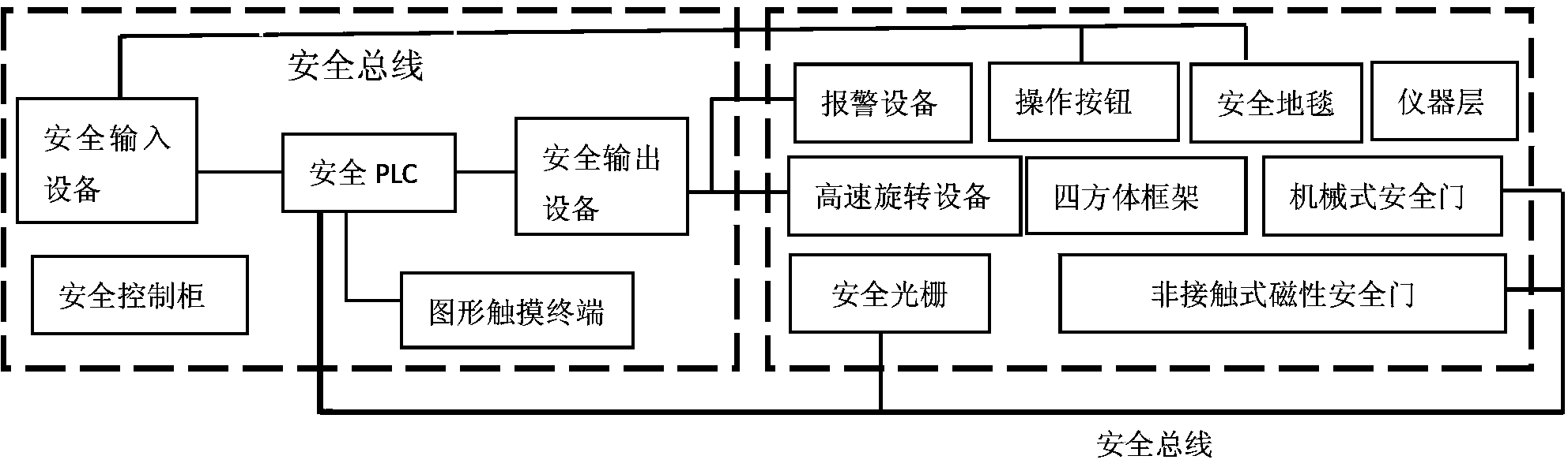
[0013] The functional safety monitoring development and demonstration system for major hazard equipment proposed by the present invention is described in detail in conjunction with the accompanying drawings and embodiments as follows:

[0014] The overall structure of the functional safety monitoring development and demonstration system for major hazard source equipment of the present invention is as follows: figure 1 As shown, the system is mainly composed of a functional safety monitoring unit I and a safety protection and demonstration unit II; the functional safety monitoring unit is used for monitoring safety parameters and processing, analyzing, judging and logically calculating the collected data, and The calculation results are output to the safety protection and demonstration unit to realize the emergency stop of high-speed rotating equipment and the linkage alarm of alarm equipment. The safety protection and demonstration unit is used to realize the collection and tr...


PUM


Abstract

The invention relates to a function safety monitoring development and demonstration system for major hazard source equipment and belongs to the technical field of function safety monitoring. The system comprises a safety control cabinet, a safe PLC (programmable logic controller) arranged in the safety control cabinet, a pattern touch terminal, safety input equipment, and safety output equipment, and also comprises a quadrangle frame and an apparatus layer which are connected into a whole up and down, a safety grating, a non-contact magnetic safety door, a mechanical safety door, an alarm device, an operation button, and a safety carpet, wherein the safety grating, the non-contact magnetic safety door and the mechanical safety door are arranged at three sides of the quadrangle frame; the alarm device is arranged above the quadrangle frame; the operation button is arranged on a panel of the apparatus layer; the safety carpet is arranged on the ground at one side of the quadrangle frame, and monitored high-speed rotation equipment is arranged inside the quadrangle frame. The system provides four effective protective measures, and problems that operating personnel enter into a danger area or various human injuries caused by misoperation are effectively avoided.

Description

technical field [0001] The invention belongs to the technical field of functional safety monitoring, in particular to a functional safety monitoring development and demonstration system. Background technique [0002] With the development of society and the deepening of people-oriented concept, safety is becoming more and more important for personnel, facilities and environment. In recent years, in the industrial fields such as masonry and machinery manufacturing, the frequent occurrence of various safety production accidents not only brought huge economic losses to enterprises and society, but also posed a great threat to people, equipment and the environment, which has become a constraint on my country's economy. An important factor in the development and construction of a harmonious society. The use of safety equipment and systems has played an important role in preventing major accidents. The reliability of these devices and systems to perform safety functions correctly ...

Claims


Application Information

Patent Timeline
Patent Type & Authority Patents(China)
IPC IPC(8): G05B19/418
CPCY02P90/02
Inventor 吴宗之魏利军方来华关磊陈丽丽
Owner CHINA ACAD OF SAFETY SCI & TECH
Features
  • R&D
  • Intellectual Property
  • Life Sciences
  • Materials
  • Tech Scout
  • Unparalleled Data Quality
  • Higher Quality Content
  • 60% Fewer Hallucinations
Learn More