Wireless communication system for determining mobile devices positions and related method

A wireless communication system and master station technology, applied in wireless communication, radio wave measurement system, transmission system, etc., can solve problems such as battery exhaustion, inability to obtain information, and low accuracy

Inactive Publication Date: 2013-01-23
FUJITSU LTD
View PDF5 Cites 10 Cited by
  • Summary
  • Abstract
  • Description
  • Claims
  • Application Information

AI Technical Summary

Problems solved by technology

[0007] However, as mentioned above, it is difficult to achieve low electrical power consumption in a mesh network
So, for example, if a transmitter used as a slave is attached to a cow in a pasture, the battery in the transmitter will run out after a while and therefore no information can be acquired
Also, in the conventional technique for acquiring an indication of a received electric field by receiving a response signal from each mobile station at a base station in response to a call from a central office, since the distance between mobile stations is not acquired, the mobile stations are specified The accuracy of the position becomes lower

Method used


Image

  • Wireless communication system for determining mobile devices positions and related method
  • Wireless communication system for determining mobile devices positions and related method
  • Wireless communication system for determining mobile devices positions and related method

Examples


no. 1 approach

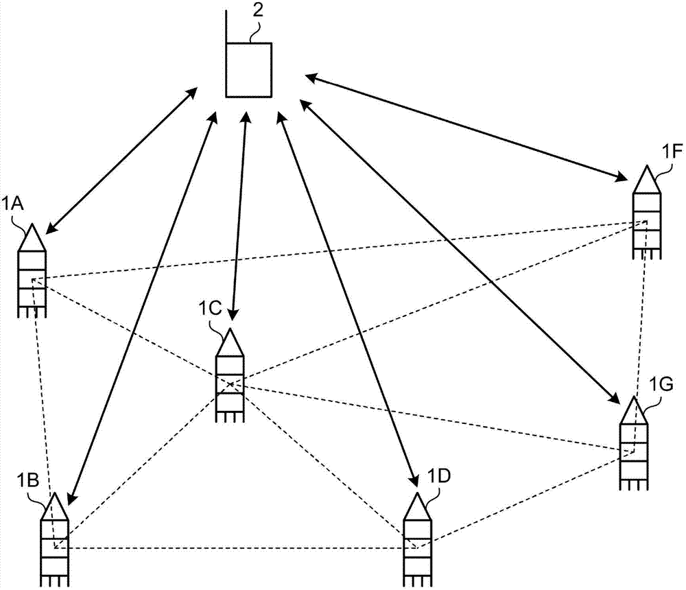
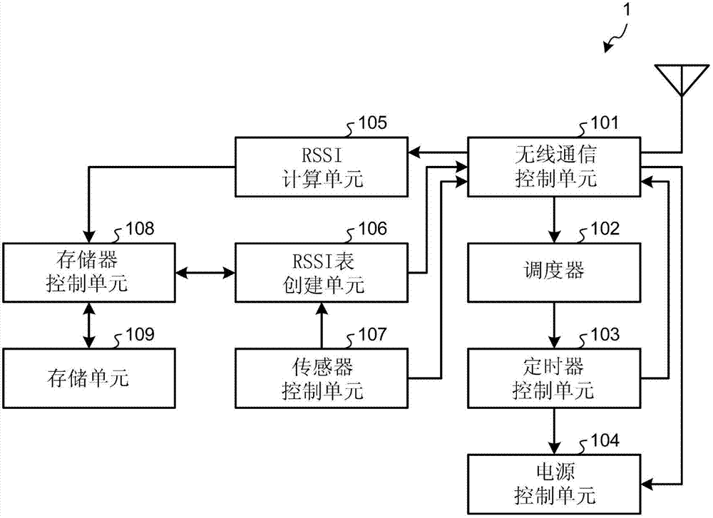
[0030] figure 1 is a schematic diagram illustrating the overall configuration of the wireless communication system according to the first embodiment. Such as figure 1 As shown, the wireless communication system according to the first embodiment includes nodes 1A to 1G which are slave stations in the wireless communication system and a hub 2 .

[0031] In the following description, a secondary station in a wireless communication system is referred to as a "node". Moreover, in figure 1 In , six nodes are illustrated. However, the number of nodes is not limited to this. exist figure 1 In , only the nodes 1A to 1G are illustrated; however, in practice, it is assumed that the nodes 1A to 1G represent n nodes.

[0032] A node number (ie, an identifier) ​​is assigned to each of the nodes 1A to 1G. In the first embodiment, for example, the nodes 1A to 1G are attached to cows, pigs, etc. and acquire ecological information such as the pulse or body temperature of the cows or pigs...

no. 2 approach

[0145] A wireless communication system according to a second embodiment will be described below. The wireless communication system according to the second embodiment is different from the first embodiment in that carrier sense multiple access (CSMA) is used as a communication method. Therefore, the following mainly describes the operation of each node when acquiring the RSSI and the operation of each node in other time slots. The node according to the second embodiment also uses figure 1 shown in the block diagram. Furthermore, the network hub according to the second embodiment also uses Figure 4 shown in the block diagram. In the second embodiment, units included in nodes and hubs having the same reference numerals as in the first embodiment have the same functions as those described in the first embodiment unless otherwise indicated.

[0146] The time at which the beacon is transmitted is stored in the scheduler 102 in the node 1 according to the second embodiment. Als...

no. 3 approach

[0205] A wireless communication system according to a third embodiment will be described below. The wireless communication system according to the third embodiment differs from the first and second embodiments in that only RSSI values ​​whose threshold is greater than a predetermined threshold are transmitted to the hub. Therefore, the following mainly describes the limitation of the RSSI value to be transmitted. The node according to the third embodiment also uses figure 1 shown in the block diagram. Furthermore, the network hub according to the third embodiment also uses Figure 4 shown in the block diagram. In the third embodiment, units included in nodes and hubs having the same reference numerals as in the first embodiment have the same functions as those described in the first embodiment unless otherwise indicated. Specifically, the functions of the hub are the same as those described in the first embodiment except for the content of the beacon transmitted to the nod...


PUM


Abstract

A wireless communication system that includes a hub and multiple nodes is provided. The nodes include a wireless communication control unit that acquires, during a predetermined communication time period, a signal transmitted to the hub by a node; an RSSI calculating unit that calculates propagation information from the signal acquired by the wireless communication control unit, and an RSSI table creating unit that transmits the calculated propagation information to the hub. The hub includes a wireless communication control unit that receives propagation information transmitted by each of the nodes and an RSSI table aggregating unit that aggregates the received propagation information.

Description

technical field [0001] Embodiments discussed herein are directed to a wireless communication system, a slave device, a master device, and a wireless communication system control method. Background technique [0002] In communication systems, network topologies such as star, tree or mesh topologies are used. Also, in a communication system, a network component such as a computer or a network hub (hub) is called a node. [0003] In a mesh network where nodes communicate equally with each other, nodes adjacent to each other communicate. Therefore, in a mesh network, when compared with a star network or a tree network, it is easy to acquire the received electric field indication (RSSI) of each transmitted signal from each node. However, in a mesh network, it is difficult to estimate when nodes communicate. Therefore, nodes need to be in a state such that they can always communicate, and thus it is difficult to sleep the entire network, which makes it difficult to achieve low ...

Claims


Application Information

Patent Timeline
Patent Type & Authority Applications(China)
IPC IPC(8): H04W52/02H04W84/20H04B17/00
CPCG01S5/0289H04B17/0072H04W64/00G01S5/0252G01S5/00A01K11/006
Inventor 横尾郁
Owner FUJITSU LTD
Why Eureka
Try Eureka