

Below-knee prosthesis provided with power ankle
A power ankle and prosthesis technology, applied in the field of below-knee prosthesis, can solve the problems of low reliability, slow braking speed of prosthesis, high noise, etc., and achieve the effects of prolonging service life, reducing energy consumption and fast braking response
- Summary
- Abstract
- Description
- Claims
- Application Information
AI Technical Summary
Problems solved by technology
Method used
Image

Examples
Embodiment 1
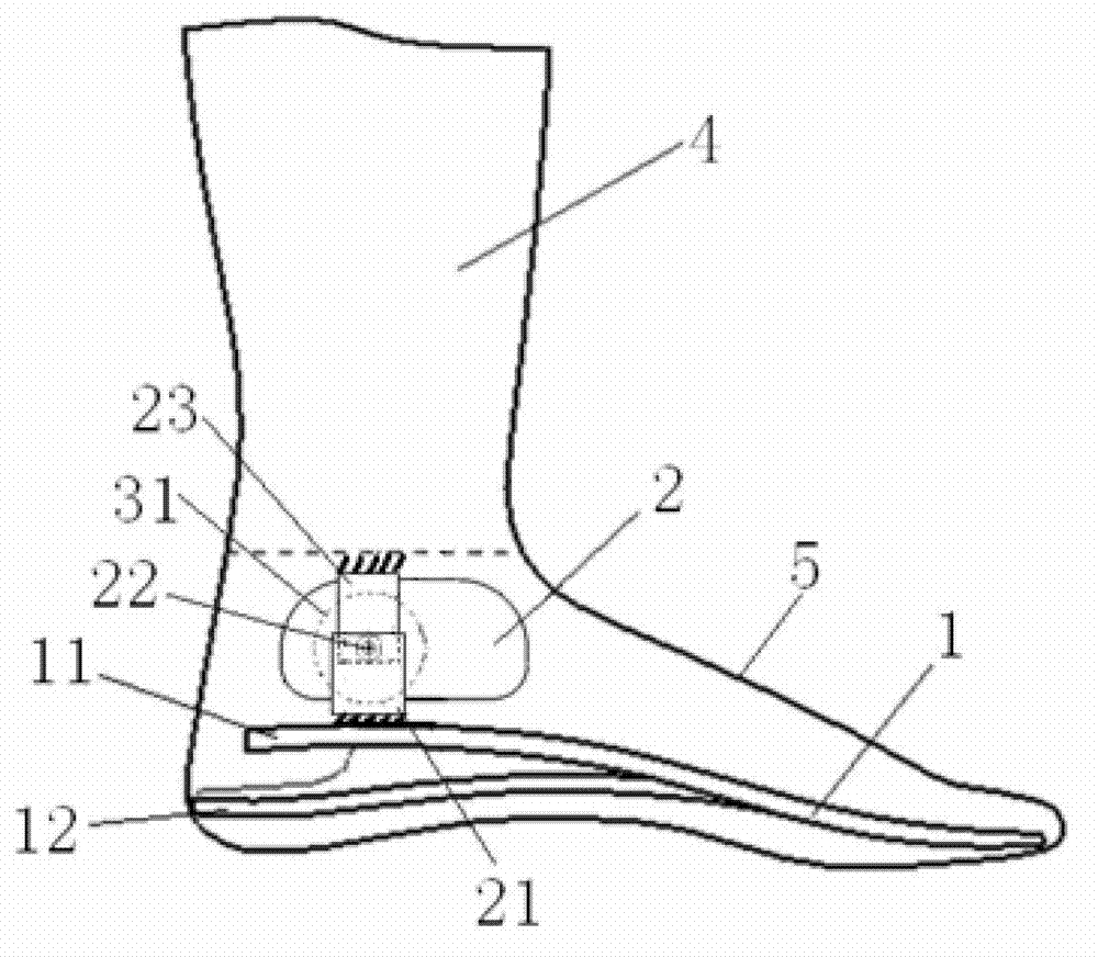
[0019] Such as figure 1 As shown, the present invention includes a prosthetic foot plate 1, an ankle joint 2 arranged on the top surface of the rear portion of the prosthetic foot plate 1 and a calf prosthesis 3 fixedly connected to the ankle joint 2, and can also include a prosthetic foot plate wrapped outside the prosthetic foot plate 1. foot cover 4.
[0020] The prosthetic foot plate 1 of the present invention comprises an upper foot plate 11 and a heel spring 12 made of a carbon fiber plate. Elastic activity space is reserved, and the front portion of the upper foot plate 11 and the lower surface of the heel shrapnel 12 are all provided with a wear-resistant layer. The prosthetic foot plate 1 of the present invention can also adopt other prior art foot plates, or foot plates made of other structural designs or materials.
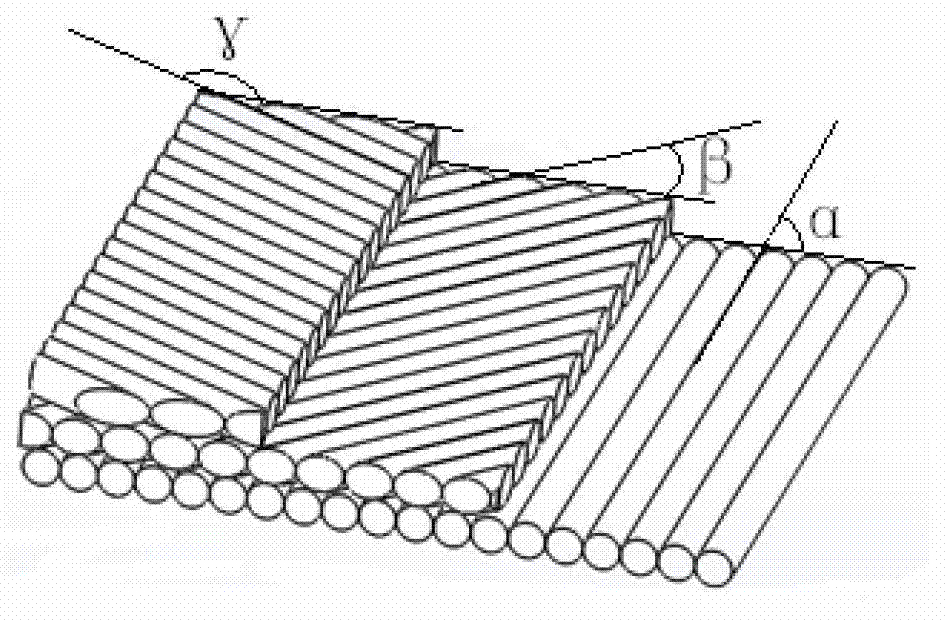
[0021] Such as figure 2 As shown, the present invention makes the carbon fiber boards of the upper foot plate 11 and the heel shrapnel 12 using car...
Embodiment 2
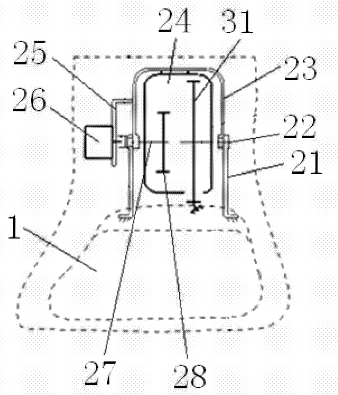
[0026] Such as Figure 5 As shown, this embodiment is basically the same as Embodiment 1, and its difference from Embodiment 1 is that in the swing frame 23, a magneto-rheological fluid tank 32 is provided on the other side of the reducer 24 opposite to the motor 26, The magneto-rheological fluid tank 32 is provided with a magnetorheological fluid, and an impeller 33 is immersed in the magnetorheological fluid. Around the rotating shaft of the impeller 33 , a coil 34 connected to a power supply device is arranged outside the magneto-rheological fluid tank 32 .
[0027] In the above embodiments, the motor 26 has an independent power supply device, and the output end of the motor 26 can rotate forward or reverse. In addition, the number of deceleration stages of the speed reducer 24 can also be increased according to needs except the structure adopted above, but the output gear of the last stage should be the incomplete gear 31.
[0028] In each of the above-mentioned embodime...
PUM
 Abstract
Description
Claims
Application Information