

Basement bottom plate having advanced-waterstop post-cast strip structure
A basement floor and post-casting technology, which is applied to underwater structures, infrastructure engineering, water conservancy projects, etc., can solve problems such as cracking, rubber waterstop position offset, expansion joint filling material deformation, etc.
- Summary
- Abstract
- Description
- Claims
- Application Information
AI Technical Summary
Problems solved by technology
Method used
Image

Examples
Embodiment 1)
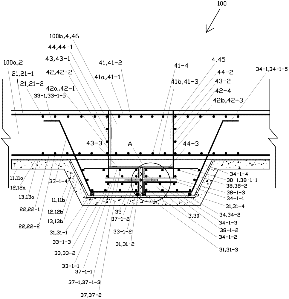
[0060] See figure 1 In this embodiment, the basement floor 100 of the advanced water-stopping post-casting strip structure is fixedly connected to the foundation of the basement. The upper surface of the foundation of the basement is composed of each datum unit and trapezoidal construction grooves with upward openings arranged between adjacent datum units. Each datum unit is located on the same horizontal plane and arranged parallel to each other. Each trapezoidal construction groove is located below the reference plane, and its upper left edge is connected with the right edge of the reference plane unit on the left, and its upper right edge is connected with the left edge of the datum unit on the right .
[0061] The basement floor 100 is composed of respective foundation floor portions 100a and respective respective post-cast tape portions 100b connected between the respective foundation floor portions 100a.
[0062] The foundation floor part 100a includes a concrete cushio...
Embodiment 2)
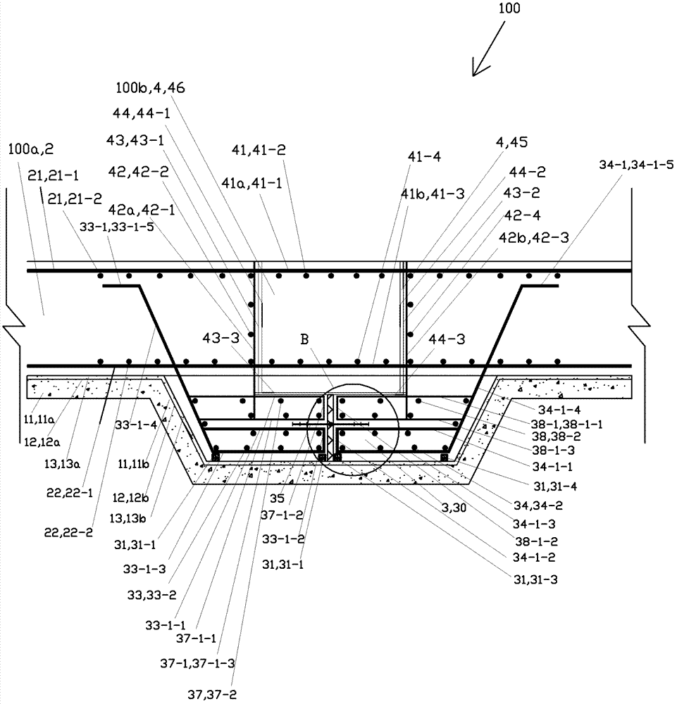
[0120] See image 3 and Figure 4 , the rest of this embodiment is the same as Embodiment 1, except that the leading waterstop 3 also includes a baffle 39 . The baffle plate 39 is divided into the lower left baffle plate 39-1 located at the lower left, the lower right baffle plate 39-2 located at the lower right, and the upper left baffle plate 39-3 located at the upper left according to the difference of the upper, lower, left, and right positions. and the upper right fender 39-4 located on the upper right. Lower left baffle plate 39-1, lower right baffle plate 39-2, upper left baffle plate 39-3 and upper right baffle plate 39-4 all have one group.
[0121] Each lower left baffle 39-1 is located on the second concrete pad 31-2 of the corresponding array of concrete pads 31, and each lower left baffle 39-1 is distributed sequentially in the front-rear direction until it penetrates in the front-rear direction The trapezoidal construction slot where it is located. Each lower...
PUM
 Abstract
Description
Claims
Application Information