
Environment-friendly clean burner

A technology of clean combustion and burner, applied in the direction of burner, gas fuel burner, combustion method, etc., can solve the problems of damage, unsatisfactory cleaning performance, low thermal efficiency, etc., to reduce temperature and oxygen concentration, and inhibit the production of harmful NO. , the effect of increasing the heat dissipation area

Active Publication Date: 2013-01-30
HANGZHOU ROBAM APPLIANCES CO LTD
View PDF5 Cites 10 Cited by
  • Summary
  • Abstract
  • Description
  • Claims
  • Application Information

AI Technical Summary

Problems solved by technology

Considering the aesthetics and other factors, the opening space of the air hole is limited. When two or more burners work at the same time, the air supply cannot meet the normal combustion requirements, and the CO concentration in the flue gas will be seriously high (current When two or more burners work at the same time in the national standard, there is no requirement, only the working state of a single burner is tested, which is different from the actual use) will have an adverse impact on the health of consumers
Secondly, the thermal efficiency is generally low (generally 50-54%), which is not energy-saving and environmentally friendly; the cleaning performance is not ideal: dirt and liquid can easily enter the inner cavity of the stove through the vent hole, which is not only very inconvenient to clean, but also easy to damage related Corrosion, damage, etc.

Method used


Image

  • Environment-friendly clean burner
  • Environment-friendly clean burner
  • Environment-friendly clean burner

Examples


Embodiment Construction

[0022] The present invention will be further described below in conjunction with the accompanying drawings and embodiments. While the invention will be described in conjunction with the preferred embodiments, it will be understood that it is not intended to limit the invention to the described embodiments. On the contrary, the invention is to cover alternatives, modifications and equivalents, which may be included within the scope of the invention as defined by the appended claims.

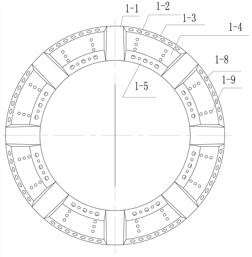
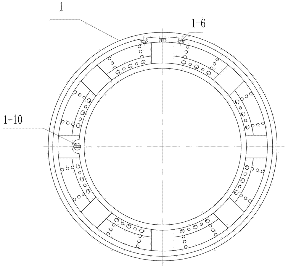
[0023] Such as Figure 1 to Figure 13 As shown, the environmentally friendly and clean burner of the present invention includes a temperature detection sensor, a copper core, a fire distributor, a hob, a burner bottom cup, a nozzle, a panel, panel fixing screws, and the like. The fire distributor is provided with 8 grooves and 8 bumps, several main fire holes are arranged on the outer slope of the bump; two rows of auxiliary fire holes are arranged on the front of the bump; several main and auxil...


PUM


Abstract

The invention discloses an environment-friendly clean burner, which comprises a copper core, a flame distributor, a furnace plate, a nozzle and a burner bottom cup in sequence from top to bottom, wherein the burner bottom cup is assembled and combined with the furnace plate, and the burner bottom cup and the furnace plate are limited and fixed through a temperature detection sensor which is fixed on the burner bottom cup and a positioning boss which is arranged on the burner bottom cup; the copper core is arranged in the center of the furnace plate; and the flame distributor is arranged on the outer ring of the furnace plate. The environment-friendly clean burner has the advantages that the requirement of one-step air supply for the burner is met, and holes do not need to be formed on other components; the air supply of the burner is realized independently without opening air inlet holes, so that an inner cavity of a cooking utensil can be kept clean, and the cleanliness of the clean burner is high; and a flame thrower is divided into a plurality of small units for sectional combustion, big and small flame outlet holes are concentrated in the different gradient surfaces of the small units, and are alternately and uniformly distributed in rows to ensure that secondary air supplementary amount is sufficient, the radiating area is enlarged, the temperature and the oxygen concentration in a high-temperature area are reduced, the generation of harmful NO is inhibited, and the heat efficiency is improved.

Description

technical field [0001] The invention relates to a burner, more specifically, it relates to an environment-friendly and clean burner. Background technique [0002] Gas stove is the main cooking tool in the family kitchen, and the key to its technical improvement or improvement is the research of burner technology. At present, most embedded gas stoves on the domestic market use burners, and the primary air inlet (i.e., the inlet of the ejector) is in the inner cavity of the bottom shell under the cooker panel; the supply of air is generally through the air hole on the rear side of the cooker panel There are also a few burners that are directly connected to the inner cavity of the cooker through the annular cavity of the secondary air channel between the outer ring fire and the copper core fire. Achieved. Considering the aesthetics and other factors, the opening space of the air hole is limited. When two or more burners work at the same time, the air supply cannot meet the no...

Claims


Application Information

Patent Timeline
IPC IPC(8): F23D14/04F23D14/46
Inventor 陈六明胡松方
Owner HANGZHOU ROBAM APPLIANCES CO LTD
Learn More