Illumination module movement device

A mobile device and lighting module technology, applied in the direction of photolithography exposure device, microlithography exposure equipment, etc., can solve the problems of large space occupation, low connection rigidity, complex structure, etc., and achieve large tilt rigidity and high positioning accuracy , the effect of structural simplification

Active Publication Date: 2013-01-30
SHANGHAI MICRO ELECTRONICS EQUIP (GRP) CO LTD
View PDF4 Cites 6 Cited by
  • Summary
  • Abstract
  • Description
  • Claims
  • Application Information

AI Technical Summary

Problems solved by technology

[0004] 1. Complex structure, long transmission chain and low efficiency;
[0005] 2. Low connection rigidity and low reliability;
[0006] 3. Occupies a large space

Method used


Image

  • Illumination module movement device
  • Illumination module movement device
  • Illumination module movement device

Examples


Embodiment Construction

[0041] In order to better understand the technical content of the present invention, specific embodiments are given together with the attached drawings for description as follows.

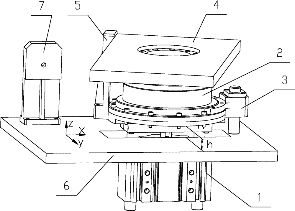
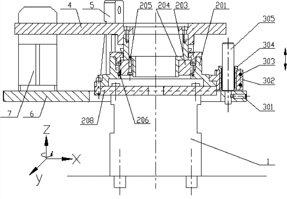
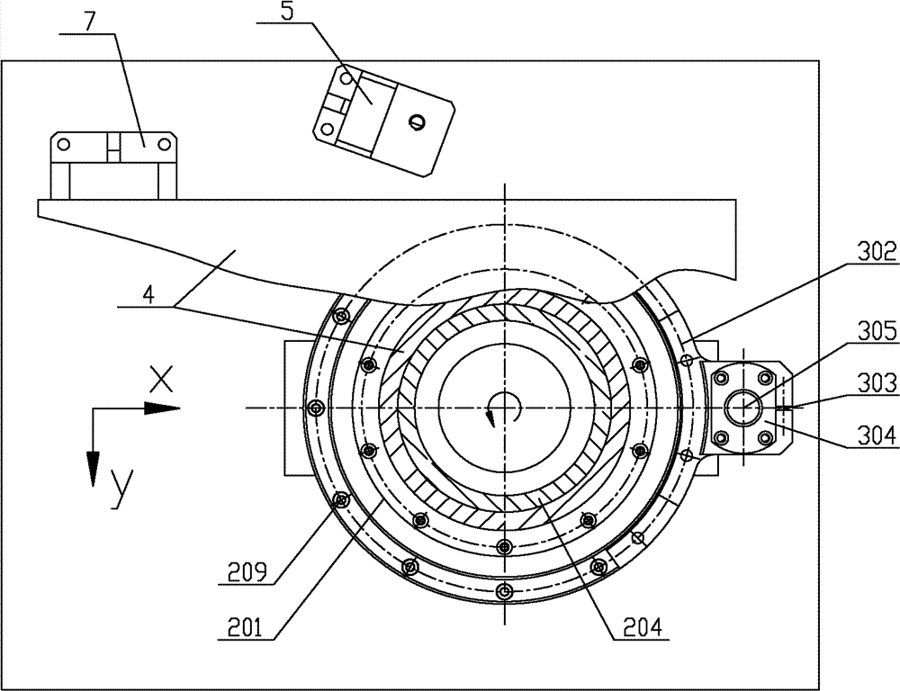
[0042] Please see figure 1 , figure 1 Shown is a schematic structural diagram of a mobile device according to a preferred embodiment of the present invention.

[0043] The moving device comprises a cylinder 1 , a rotating unit 2 , a guide module 3 , a bearing plate 4 , a first limiting block 7 , a second limiting block 5 and a base 6 .

[0044] The lighting module (not shown in the figure) is arranged on the carrying board 4 , and the carrying board 4 leans against the first limiting block 7 . The cylinder 1 drives the rotary unit 2 in the Z direction. After the rotating unit 2 is lifted by a fixed distance h, the bearing plate 4 can be rotated, and then the bearing plate 4 can be leaned against the second limit block 5 . The user can lock the bearing plate 4 on the second limit block 5 to perf...


PUM


Abstract

The invention provides an illumination module movement device. The device comprises a pedestal, a first stop block, a second stop block, a loading plate, a cylinder and a rotary unit, wherein the first stop block and the second stop block are respectively fixed on the pedestal; the loading plate leans against the first stop block; the rotary unit loads and rotates the loading plate; the cylinder is connected with the rotary unit and drives the rotary unit along a Z direction; and the rotary unit rotates the loading plate to make the loading plate lean against the second stop block when the cylinder drives the rotary unit to a fixed distance along a +Z direction. The illumination module movement device provided by the invention can rapidly lift and rotate an illumination top module and has a high repeated positioning precision.

Description

technical field [0001] The invention relates to a moving device, and in particular to a moving device for an illumination module of a lithography machine. Background technique [0002] In a stepping or scanning lithography machine, since the illumination module is generally above the mask table, and the vertical space is small, if it is necessary to maintain and repair the mask table, such as wiping the plate holder of the mask table , cleaning, maintenance, repair, replacement and installation of the drive motor and cylinder, etc., the lighting module and alignment module on the upper part of the mask table must be removed first to expose the maintenance and repair parts of the mask table. After the maintenance or repair work is completed Then restore the lighting module to its original position. Therefore, the moving in and out of the lighting module needs to ensure sufficient repeat positioning accuracy, so as to ensure the rapid recovery of the whole machine. [0003] ...

Claims


Application Information

Patent Timeline
IPC IPC(8): G03F7/20
Inventor 黄静莉
Owner SHANGHAI MICRO ELECTRONICS EQUIP (GRP) CO LTD
Why Eureka
Try Eureka