
Organic light-emitting diode (OLED) display and method for coating polarizing film of OLED display

A diode and display technology, applied in electronic equipment, electric solid state devices, instruments, etc., can solve the problems of easy generation of air bubbles, decreased contrast, and generation of air bubbles, and achieves the effect of avoiding air bubbles and improving yield.

Active Publication Date: 2013-01-30
TCL CHINA STAR OPTOELECTRONICS TECH CO LTD
View PDF4 Cites 15 Cited by
  • Summary
  • Abstract
  • Description
  • Claims
  • Application Information

AI Technical Summary

Problems solved by technology

[0002] OLED (Organic Light Emitting Diode) displays need to vapor-deposit a layer of metal electrodes on the light-emitting surface to form diodes. However, this layer of metal will cause users to be affected by external light reflection when viewing OLED displays, which will reduce the contrast. Affects viewing quality, especially under strong light or outdoors, so whether it is a top-emitting or bottom-emitting AMOLED display, it is necessary to attach a polarizer to block the reflection of external light
[0003] In the prior art, the method of pasting the polarizer is to first make the adhesive layer on the polarizer, and then attach the adhesive layer to the organic electroluminescent diode device. However, this method of pasting the polarizer is easy Bubbles are generated between organic electroluminescent diode devices, especially when the substrate is a flexible substrate. Because the softness of the flexible substrate and the polarizer is different, bubbles are more likely to be generated during bonding, resulting in a very low yield rate in the polarizer process.

Method used


Image

  • Organic light-emitting diode (OLED) display and method for coating polarizing film of OLED display
  • Organic light-emitting diode (OLED) display and method for coating polarizing film of OLED display
  • Organic light-emitting diode (OLED) display and method for coating polarizing film of OLED display

Examples


Embodiment Construction

[0021] The following will clearly and completely describe the technical solutions in the embodiments of the present invention with reference to the accompanying drawings in the embodiments of the present invention. Obviously, the described embodiments are only some, not all, embodiments of the present invention. Based on the embodiments of the present invention, all other embodiments obtained by persons of ordinary skill in the art without making creative efforts belong to the protection scope of the present invention.

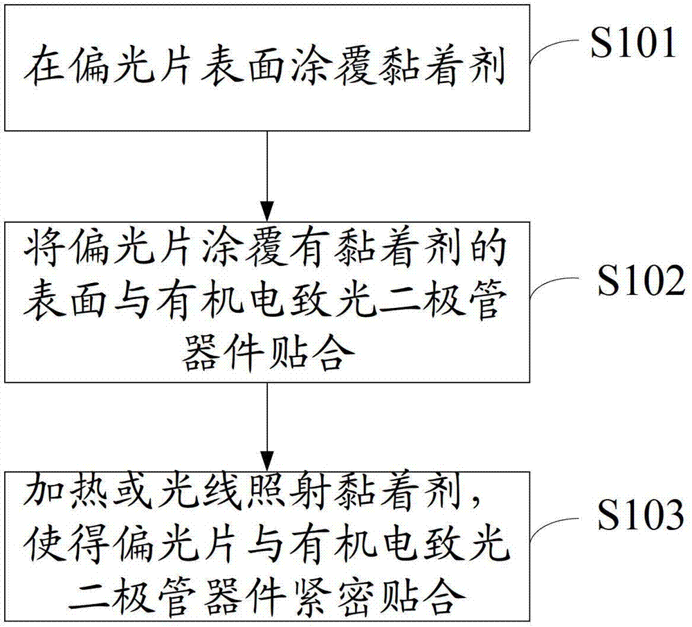
[0022] see figure 1 , figure 1 It is a schematic flow chart of an embodiment of a method for attaching a polarizer of an organic electroluminescence diode display according to the present invention. The organic electroluminescent diode display includes but not limited to an organic electroluminescent diode device. The organic electroluminescent diode device includes a substrate, an organic electroluminescent diode film layer and a thin film encapsulation laye...


PUM


Abstract

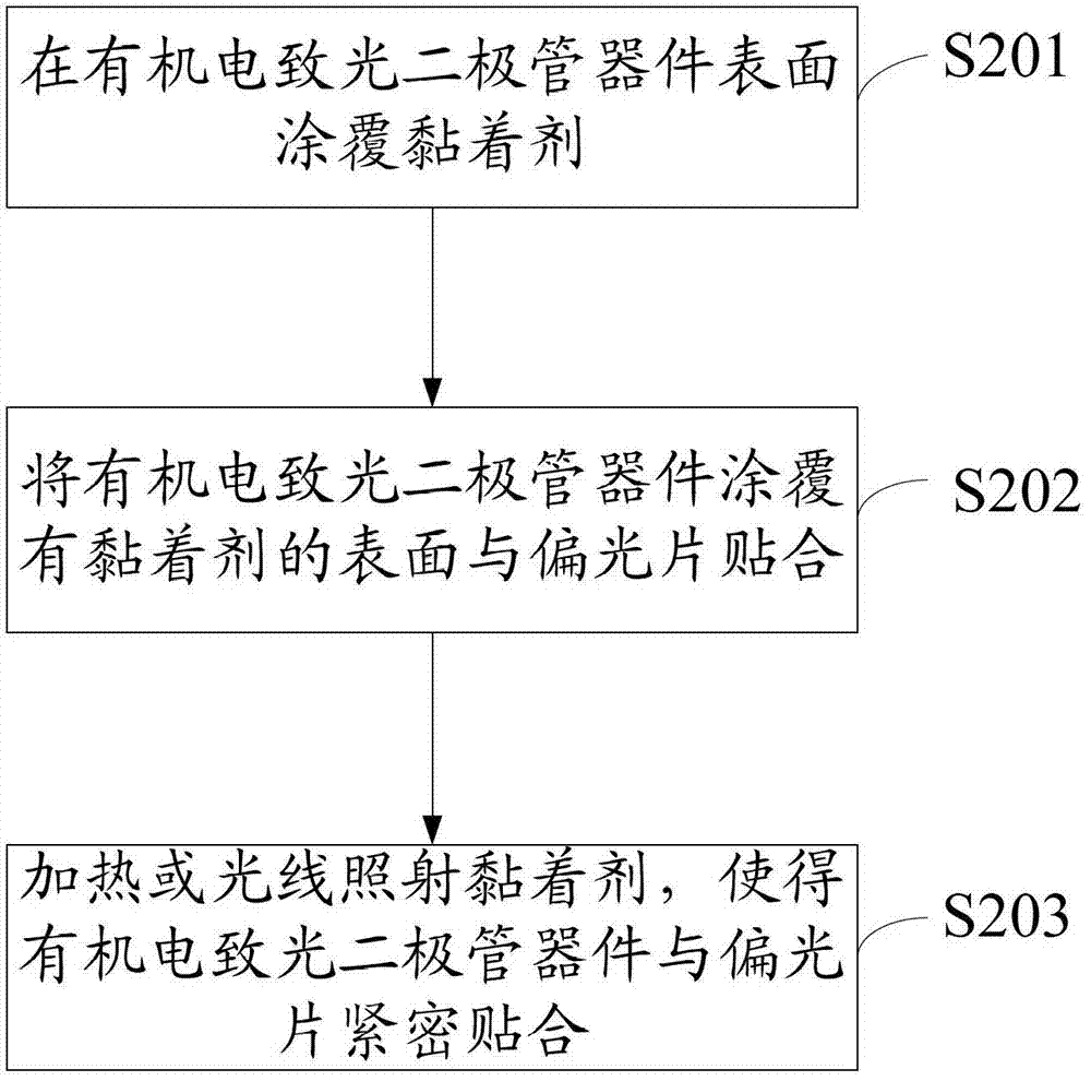
The embodiment of the invention discloses a method for coating a polarizing film of an organic light-emitting diode (OLED) display. The OLED display comprises an OLED device. The method mainly comprises the following steps of: coating an adhesive on the surface of the polarizing film; attaching the surface of the polarizing film, on which the adhesive is coated, to the OLED device; and heating or irradiating the adhesive, so the polarizing film is tightly attached to the OLED device. The embodiment of the invention also discloses the OLED display. The method and the OLED display have the advantages that bubbles can be prevented from being generated in a polarizing film coating process, and the yield of the polarizing film coating process is improved.

Description

technical field [0001] The invention relates to the technical field of polarizer cladding, in particular to an organic electroluminescent diode display and a polarizer cladding method thereof. Background technique [0002] OLED (Organic Light Emitting Diode) displays need to vapor-deposit a layer of metal electrodes on the light-emitting surface to form diodes. However, this layer of metal will cause users to be affected by external light reflection when viewing OLED displays, which will reduce the contrast. Affects the viewing quality, especially under strong light or outdoors, so whether it is a top-emitting or bottom-emitting AMOLED display, it is necessary to attach a polarizer to block the reflection of external light. [0003] In the prior art, the method of pasting the polarizer is to first make the adhesive layer on the polarizer, and then attach the adhesive layer to the organic electroluminescent diode device. However, this method of pasting the polarizer is easy ...

Claims


Application Information

Patent Timeline
IPC IPC(8): H01L27/32H01L51/56
CPCG02B5/3033B32B7/12B32B2307/42B32B2457/206H10K59/8791
Inventor 刘至哲吴元均
Owner TCL CHINA STAR OPTOELECTRONICS TECH CO LTD
Learn More