System and method for implementation of control channel resource allocation
A technology for controlling channel resources and control channels, which is applied in the field of realizing control channel resource allocation, and can solve problems such as waste of transmission resources
- Summary
- Abstract
- Description
- Claims
- Application Information
AI Technical Summary
Problems solved by technology
Method used
Image

Examples
Embodiment 1
[0056] Such as image 3 As shown, the R8 / R9 / R10 UEs are not scheduled in the ABS configured in the embodiment of the present invention, and RRC signaling is used to indicate whether the UE performs blind detection from the first OFDM symbol.
[0057] In this case, the process of E-PDCCH resource configuration and user detection is as follows:
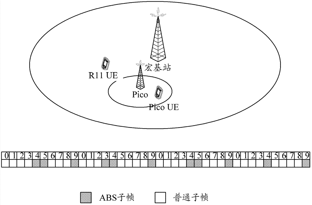
[0058] The MeNB sends ABS configuration information to the UE of R11. The ABS configuration method can be a 40-bit bitmap, where each bit corresponds to a subframe, and 40 bits correspond to 40 subframes in total, such as image 3 As shown, 1 can be used to represent ABS and 0 can be used to represent non-ABS, that is, the bitmap of ABS in the figure can be configured as:
[0059] [0 0 0 0 1 1 0 0 0 1 0 0 0 1 1 0 0 0 0 1 0 0 0 0 1 1 0 0 0 1 0 0 0 0 1 0 0 0 0 1].
[0060] This kind of bitmap can be several pre-configured patterns, each pattern is represented by an index number, and the method of notifying the index number can be used ...
Embodiment 2
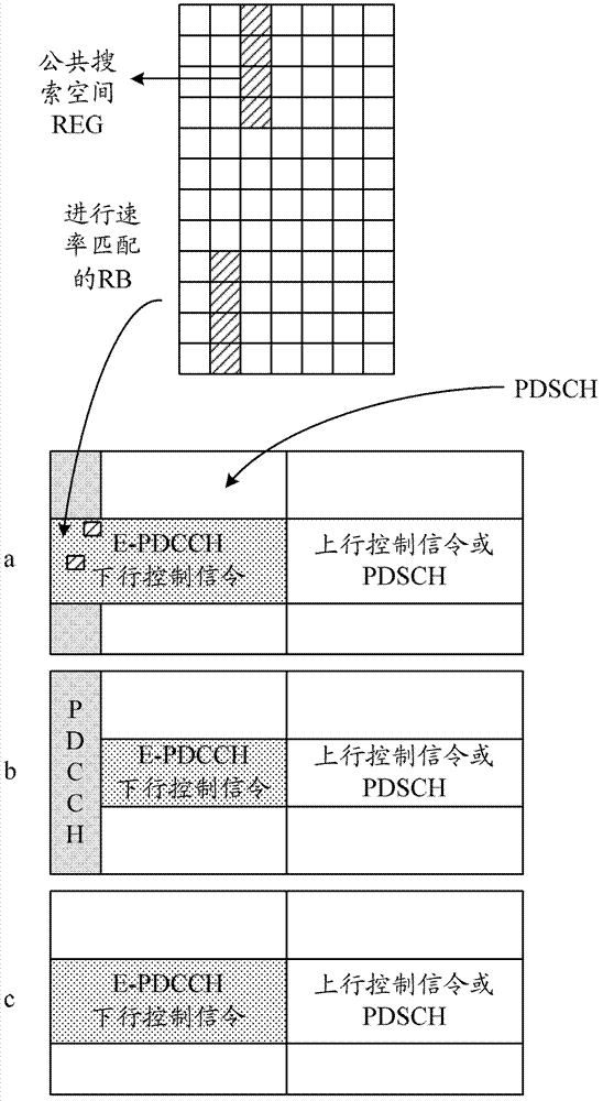
[0069] Different from Embodiment 1, in this embodiment, the number of symbols occupied by the PDCCH indicated by the CFI is configured as 0 to indicate whether the mapping of the E-PDCCH starts from the first OFDM symbol of the current subframe. Such as Figure 4 As shown, in the embodiment of the present invention, the position of the start symbol of the E-PDCCH and the corresponding PDSCH is indicated by the PCFICH. The CFI indication shown in Table 1 is configured in the existing 3GPP protocol 36.212:
[0070] Table 1. The number of PDCCH symbols indicated by CFI and their codeword correspondence
[0071]
[0072] The all-zero sequence codeword with CFI configured as 4 reserved in Table 1 can be used to indicate that the current E-PDCCH is mapped from the first OFDM symbol of the current subframe, that is, the number of OFDM symbols occupied by the PDCCH is 0.
[0073] In this case, the process of E-PDCCH resource configuration and user detection is as follows:
[0074]...
Embodiment 3
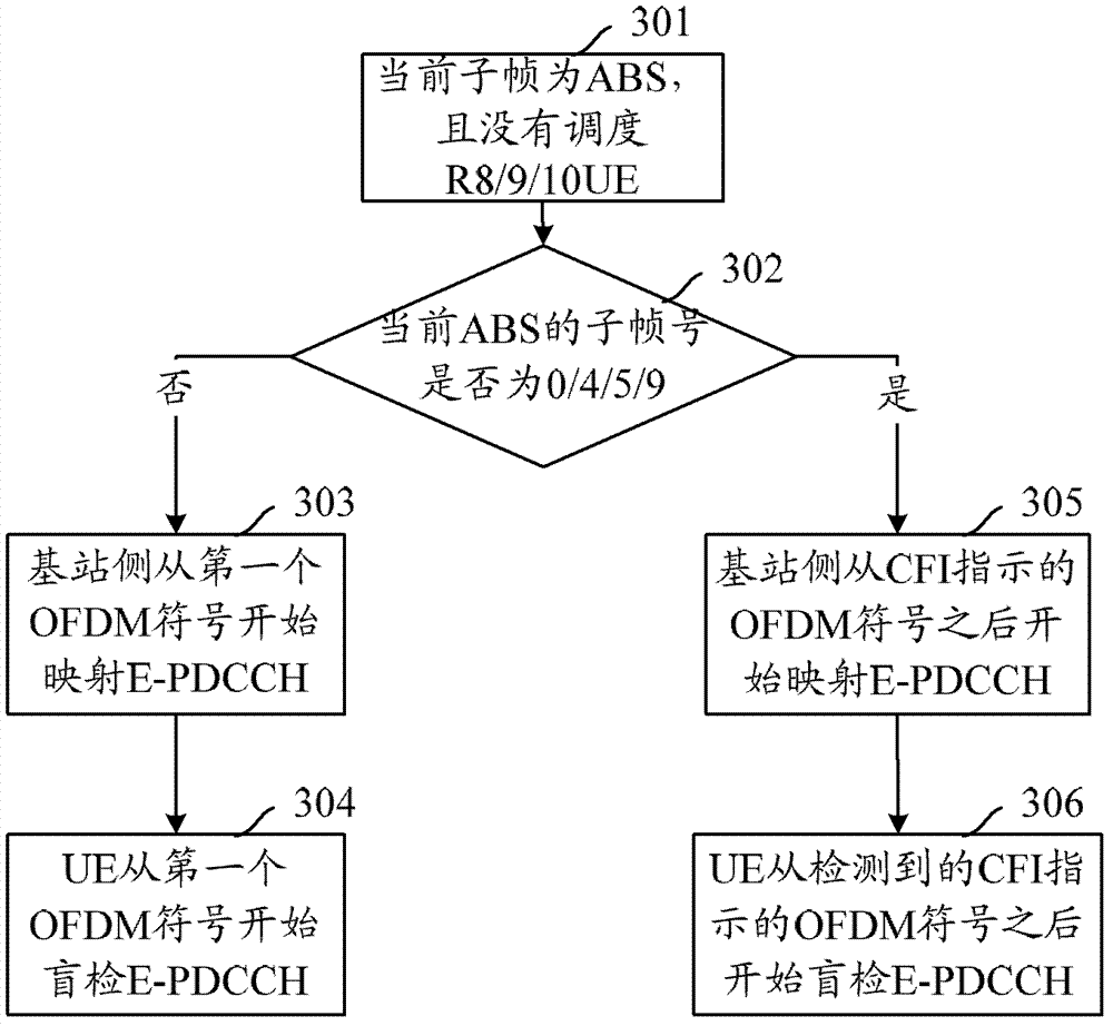
[0081] What is different from Embodiment 2 is that in this embodiment, CFI is not used to indicate whether to map E-PDCCH from the first OFDM symbol of the current ABS subframe, but RRC signaling is used to inform UE which subframes are in the form of ABS bitmap. Frame time ABS. Different from Embodiment 1, in this embodiment, in subframes 0, 4, 5, and 9, the E-PDCCH is not mapped from the OFDM symbol after the PDCCH, but always starts from the first OFDM symbol. Such as Figure 5 As shown, in the embodiment of the present invention, the MeNB does not schedule R8 / 9 / 10 UEs in the ABS. In ABS, the E-PDCCH and PDSCH of R11 UEs are always mapped from the first OFDM symbol. At this time, it is necessary to notify the R11 UE of the ABS configuration through RRC signaling, so that the UE can know the subframe mapped from the first symbol.
[0082] In this case, the process of E-PDCCH resource configuration and user detection is as follows:
[0083] Step 501: judging that the curr...
PUM
 Abstract
Description
Claims
Application Information
PatSnap Eureka turns technology decisions into work you can execute. Powered by our Innovation Knowledge Graph, it runs expert workflows across engineering, life sciences, materials and intellectual property. Get your review-ready output in minutes.


