
Metal casting device

A technology of metal casting and driving device, applied in the field of metal casting of high melting point metal and metal casting device, can solve the problems of large body, damaged joint surface, poor contact, etc., and achieves the effect of simple structure, small size and improved safety.

Inactive Publication Date: 2013-02-06
SINOSTEEL LUOYANG INST OF REFRACTORIES RES
View PDF5 Cites 6 Cited by
  • Summary
  • Abstract
  • Description
  • Claims
  • Application Information

AI Technical Summary

Problems solved by technology

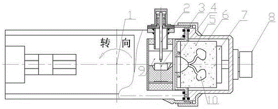
[0004] The first type: centrifugal pressure casting machine, such as figure 1 Shown: after the melting of the metal block 3 is completed, the molten metal is thrown into the cavity 10 in the mold 5 through rotation by centrifugal action; at the same time, high-pressure argon gas is added in the melting cavity 9 to make the metal better melt The cavity 10 is full; due to the existence of the centrifugal device, the body of the mechanism is large and the structure is complex
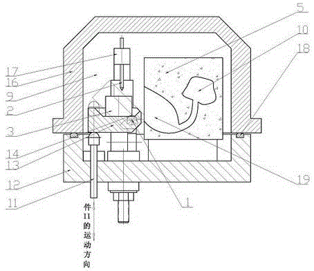
[0005] The second type: differential pressure casting machine, such as figure 2 : a casting mold and a crucible are set inside the melting chamber 6 that can control the internal pressure, wherein the crucible is positioned at one side of the casting mold; after the melting of the metal block 3 is completed, the crucible 4 is lifted to make the crucible tilt toward the storage cavity 19 of the casting mould, so that the melting The metal flows into the storage cavity 19 of the mold 5, and then high-pressure argon is applied to make the molten metal flow into the cavity 10 from the storage cavity 19 to form a casting; During the inclination process at the cavity 19, it rotates around the center of the rotating shaft 1, but the current does not stop, and arcing is particularly likely to occur at the joint surface 14 between the crucible and the rotating shaft, which will damage the joint surface and cause poor contact.
[0006] When the above mechanisms are in operation, there is a process of vacuuming; when the high-temperature titanium liquid is injected into the mold, a large amount of smoke will be generated. Service life of solenoid valves and vacuum pumps

Method used


Image

  • Metal casting device
  • Metal casting device
  • Metal casting device

Examples


Embodiment Construction

[0029] The present invention is described in conjunction with accompanying drawing and specific embodiment:

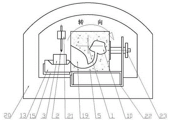
[0030] like image 3 , Figure 4 As shown, a metal casting device, the casting chamber 6 is formed between the shell 20 and the front door 29 of said metal casting device; The ring II 28 is used to ensure reliable sealing between the housing 20 and the front door 24; the crucible 13 and the casting mold 5 are arranged in the casting chamber 6; 19 is provided correspondingly; the casting mold 5 is placed on the casting mold support 22; the casting mold 5 has a storage chamber 19 and a casting molding cavity 10 for molding the casting; it is set above the crucible 13 for passing through Arc discharge is used to melt the tungsten pole 2 placed on the metal block 3 in the crucible; the tungsten pole 2 is fixed on the cathode shaft 21; the cathode shaft 21 is connected to the cable outside the housing 20 through the cathode insulating sleeve 26; the The crucible 13 is pl...


PUM


Abstract

The invention belongs to the technical field of metal casting and provides a metal casing device. The metal casting device is provided with a melting and casting chamber in which a crucible (13) and a casting mold (5) are arranged, wherein the melting and casting chamber (6) is in a structure capable of swinging at a certain angle under the action of a driving device; the crucible (13) and the casting mold (5) which are disposed in the melting and casting chamber (6) can swing at a certain angle along with the melting and casting chamber; molten metal flows into a storage chamber (19) of the casting mold from the crucible during swinging with the melting and casting chamber; and pressure gas is fed into the melting and casting chamber (6) through a gas inlet (25) in the center of a spindle so that the molten metal flown into the storage chamber of the casting mold is pressed into a cast molding cavity (10) of the casting mold to form casts. According to the metal casing device, parts do not move relatively in pouring process, so that damage to equipment due to arc striking in pouring process in the prior art can be avoided. Compared with the centrifugal pressure casting machine in the prior art, the metal casing device has the advantages of being simple in structure and small in size.

Description

technical field [0001] The invention belongs to the technical field of metal casting, relates to metal casting of high-melting point metals, and mainly relates to a metal casting device. Background technique [0002] At present, the application of high-melting-point metal materials in many fields is becoming more and more popular. For example, when repairing damaged or lost teeth, the repair materials used are high-melting-point metals, such as titanium, zirconium, platinum, etc., or their alloys. Among the materials, titanium is the most suitable material due to considerations of strength, weight, corrosion resistance, biocompatibility, and price, and thus has been widely used. When utilizing this type of high-melting point metal material for casting, the general practice is: make a mold with a cavity of required shape with a refractory material, inject molten metal into the cavity to form a casting, then destroy the mold and take out the casting. [0003] The institutions...

Claims


Application Information

Patent Timeline
IPC IPC(8): B22D17/20B22D17/22
Inventor 张国靖郭楠王江涛吴晓光孟烨
Owner SINOSTEEL LUOYANG INST OF REFRACTORIES RES
Learn More