Supercharge Your Innovation With Domain-Expert AI Agents!

High-speed electric spindle with outer rotor structure

A high-speed motorized spindle and outer rotor technology, applied in electrical components, electromechanical devices, and electrical components, etc., can solve the problems of insufficient rigidity, inability to improve processing efficiency, and reduced processing accuracy.

Inactive Publication Date: 2013-02-06
SHANGHAI UNIV
View PDF5 Cites 5 Cited by
  • Summary
  • Abstract
  • Description
  • Claims
  • Application Information

AI Technical Summary

Problems solved by technology

[0004] In order to solve the problems of the prior art, the object of the present invention is to overcome the deficiencies existing in the prior art, and provide a high-speed electric spindle with an outer rotor structure, which overcomes the processing conditions of the traditional inner rotor structure electric spindle for deep holes and deep cavities. Due to the defects of insufficient rigidity, reduced machining accuracy, and inability to improve machining efficiency, a high-speed electric spindle with an outer rotor structure suitable for cutting the inner surface of deep holes and deep cavities is provided to improve the stiffness of the spindle under high-speed rotation conditions, making the inner Surface machining accuracy and machining efficiency can be improved

Method used


Image

  • High-speed electric spindle with outer rotor structure
  • High-speed electric spindle with outer rotor structure

Examples


Embodiment 1

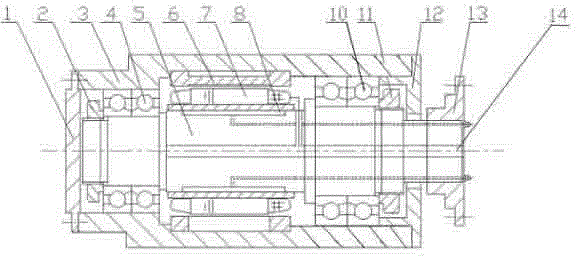
[0018] see figure 1 , a high-speed electric spindle with an outer rotor structure, including a motor spindle 5, the motor spindle 5 is used as a mandrel for installing the inner stator of the motor, and the inner stator 7 of the motor is installed on the internal fixed motor spindle 5 to form the stator part of the motor, and The motor rotor part includes the motor outer rotor 6 and the casing 3. The motor outer rotor 6 is installed on the periphery of the motor inner stator 7 to rotate. The motor outer rotor 6 is fastened inside the casing 3 and drives the casing 3 to rotate together. Between the casing 3 and the motor shaft 5 The two groups of bearings 4 and 10 are used to support the front and rear. The outer rings of the bearings 4 and 10 are fixedly connected to the casing 3. The outer end faces of the inner rings of the bearings 4 and 10 facing the two ends of the motor main shaft 5 are connected to the motor main shaft through the bearing sleeves 2 and 11 respectively. ...

Embodiment 2

[0023] This embodiment is basically the same as Embodiment 1, especially in that:

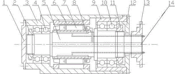
[0024] see figure 2 , in this embodiment, the front section of the casing 3 that is installed near the front end of the motor shaft 5 with the outer ring of the bearing 4 forms a force transmission section, the middle section of the casing 3 that is installed with the outer rotor 6 of the motor forms a power generation section, and the section near the rear end of the motor shaft 5 The rear part of the shell 3 of the outer ring of the bearing 10 forms the disturbance control section of the hollow shaft head rotor system, and the thickness of the shell 3 of the force transmission section and the power generation section is greater than the thickness of the shell 3 of the disturbance control section. A rear bearing seat 9 is also provided inside the housing 3 of the section, and the housing 3, the outer ring of the bearing 10 and the rear end cover 12 are fastened and installed and connected by ...


PUM


Abstract

The invention discloses a high-speed electric spindle with an outer rotor structure, wherein a motor spindle is used as a mandrel for installing a motor inner stator; the motor inner stator is installed on the motor spindle the interior of which is fixed to form a motor stator part; a motor rotor part comprises a motor outer rotor and a housing; the motor outer rotor is installed on the periphery of the motor inner stator to rotate, fastened in the housing, and used for driving the housing to rotate together so as to form a hollow spindle-head rotor system which integrally rotates; a working assembly is installed and connected close to the outer circle of the front end of a front end cover; and the rear end of the motor spindle penetrates through the central hole of a rear end cover and overhangs outside the hollow spindle-head rotor system so as to form a combination part capable of being fixedly connected with external equipment. According to the high-speed electric spindle, the defects of insufficient rigidity, reduction of machining accuracy and incapacity of improving the machining efficiency when the conventional electric spindle with an inner rotor structure is used for machining a deep-hole and deep-cavity inner surface are overcome, and the rigidity of the spindle is improved under the condition of high-speed rotation, so that the machining accuracy and the machining efficiency are improved.

Description

technical field [0001] The invention relates to an electric spindle, in particular to a high-speed electric spindle applicable to machine tools for processing the inner surface of deep holes and deep cavities, and can be widely used in machining centers. Background technique [0002] The high-speed electric spindle is a functional component that integrates the tool spindle and the drive motor to realize the integration of the motor and the spindle. For workpieces with deep holes and deep cavities, the grinding and other cutting processing of the inner surface has always been one of the problems faced by the related manufacturing engineering field. If a high-speed electric spindle with an ordinary inner rotor structure is used, the cutting tools such as grinding wheels are directly Installed on an overhanging spindle, due to the limitation of the size of the deep hole and deep cavity, the rigidity of the overhanging spindle on which the cutting tool is installed is low, which...

Claims


Application Information

Patent Timeline
IPC IPC(8): B23B19/02H02K5/16H02K9/19
Inventor 李松生董玛莉鲁豫鑫邵娟俞锋
Owner SHANGHAI UNIV
Features
  • R&D
  • Intellectual Property
  • Life Sciences
  • Materials
  • Tech Scout
  • Unparalleled Data Quality
  • Higher Quality Content
  • 60% Fewer Hallucinations
Learn More