Conveying line device with function of retaining workpieces temporarily

A technology for transmission lines and workpieces, applied in the field of transmission lines, can solve the problems of reduced turning force, reduced equipment use efficiency, damage to friction strips, etc.

Inactive Publication Date: 2013-02-06
大连奥托股份有限公司
View PDF6 Cites 3 Cited by
  • Summary
  • Abstract
  • Description
  • Claims
  • Application Information

AI Technical Summary

Problems solved by technology

It is obviously unrealistic to stop and start the production line frequently, so in order to achieve the above purpose, the traditional transmission line adopts the method of setting a friction groove wheel with a groove on the driven shaft, and a The flipping friction strip matched with the friction groove wheel relies on the static friction force provided by the friction strip to make the supporting plate move with the rotation of the friction groove wheel. When the positioning device set on the frame is working, a supporting plate is blocked. The friction mode between the friction strip on the board and the friction groove wheel changes from static friction to dynamic friction, and the chain continues to move. After the work of the next station is completed, the positioning device is removed, and the friction force between the friction strip and the friction groove wheel resumes It turns into static friction, and the pallet continues to move forward; although the above structure can realize the function of buffering workpieces, the friction strips are easily damaged during frequent work and need to be replaced frequently, resulting in reduced equipment use efficiency
At the same time, the turning process of the pallet at both ends of the frame also relies on the friction strips to provide power. After the equipment has been working for a period of time, the turning force that the friction strips can provide gradually decreases, and there are certain hidden dangers and problems.

Method used


Image

  • Conveying line device with function of retaining workpieces temporarily
  • Conveying line device with function of retaining workpieces temporarily
  • Conveying line device with function of retaining workpieces temporarily

Examples


Embodiment Construction

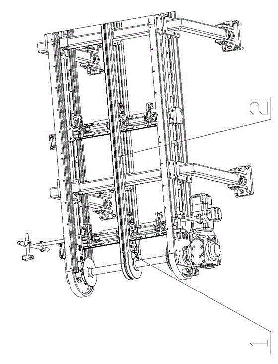
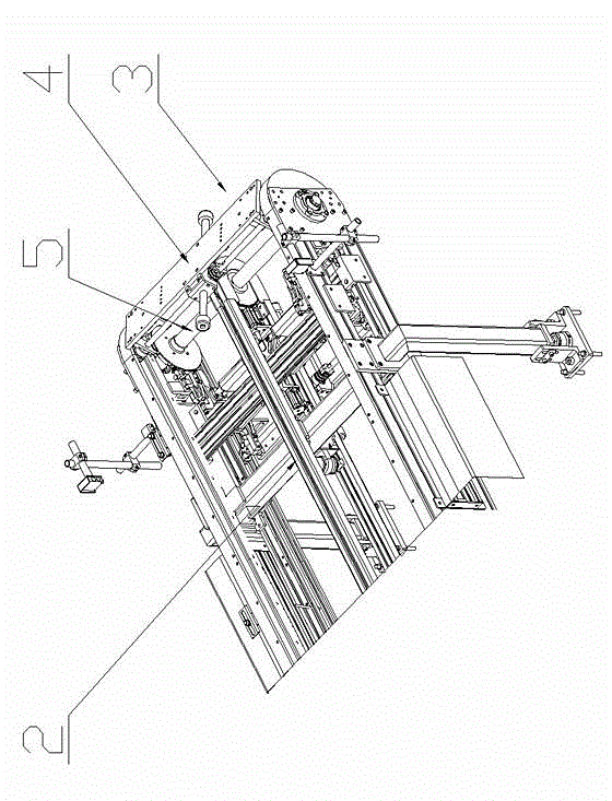
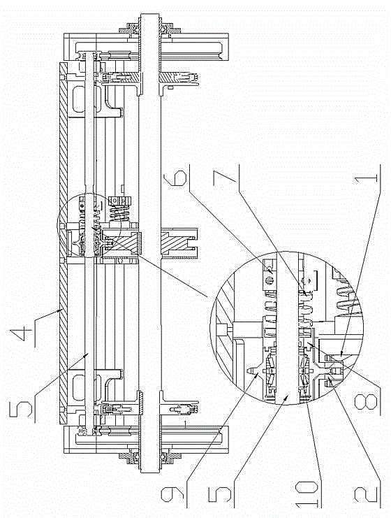
[0012] The specific implementation manner of the present invention will be described below with reference to the accompanying drawings. Such as figure 1 , figure 2 , image 3 , Figure 4 , Figure 5 Shown: a transmission line device with the function of buffering workpieces, which includes a frame as a base, a drive motor is arranged at one end of the frame, the drive motor drives the driving wheel to rotate through the reduction box, and the driving wheels set in pairs are Drive the set drive shaft between them to rotate (such as figure 1 As shown), a driven wheel 1 is arranged on the driving shaft, and the driven wheel 1 drives the chain 2 meshed with it to move, and a plurality of brackets 3 are arranged equidistantly on the chain 2, and a positioning wheel is also arranged on the frame device, the bracket 3 used to transport the workpiece is composed of a support plate 4 on the upper part and a support shaft 5 on the lower part, and a fixed seat 6 is fixedly arranged...


PUM


Abstract

The invention discloses a conveying line device with a function of retaining workpieces temporarily. A tradition structure with friction strips and friction furrow wheels is abandoned and replaced by an annular friction disc and an idle gear meshed with a chain. A round turning disc is disposed at one end of a drive shaft of a frame to enable the conveying line device to be more reliable and smooth in turning. Profiling blocks matched with pins disposed on the turning disc are disposed on two sides of a support frame. Turning of the support frame is realized by inserting pins into turning holes on the profiling blocks. The conveying line device with the function of retaining workpieces temporarily is simple in structure, ingenious in design, and reasonable in layout. A damping (spring) structure is used for driving the support frame to move, the pins and turning holes are used for driving the support frame to turn, and accordingly moving is more reliable, and operation complexity caused by frequent replacing of friction strips can be avoided.

Description

technical field [0001] The invention relates to a transmission line, in particular to a transmission line device with the function of buffering workpieces. Background technique [0002] Transmission line equipment is one of the main equipment on the automobile welding assembly line. The structure of the traditional transmission line equipment is: there is a frame as the foundation, a driving shaft connected to the reducer and a motor is installed at one end of the frame, and a driven shaft is installed at the other end of the frame; There is a chain transmission device between the shafts, and the chain transmission device is matched with a supporting plate that directly transports the workpiece, that is, the supporting plate circulates under the drive of the chain to transport the workpiece from one end of the frame to the other end. And sometimes according to actual work needs, the movement of supporting plate can not be continuous, and needs to stop in situ somewhere on t...

Claims


Application Information

Patent Timeline
Patent Type & Authority Applications(China)
IPC IPC(8): B65G47/24B65G47/248
Inventor 王明墩王永预王涛胡勇刚
Owner 大连奥托股份有限公司
Why Eureka
Try Eureka