Process device for electroplating air valves

A technology of process equipment and electroplating equipment, which is applied in the direction of electrolysis process, electrolysis components, etc., can solve the problems of difficult maintenance of conductive devices, difficult removal of oxide scales on conductive heads, inconvenient assembly and disassembly, etc., so as to improve the utilization rate of equipment and the intact rate of equipment , shorten the auxiliary time, reduce the effect of maintenance time

Inactive Publication Date: 2013-02-06
鹰普航空科技(南通)有限公司
View PDF5 Cites 4 Cited by
  • Summary
  • Abstract
  • Description
  • Claims
  • Application Information

AI Technical Summary

Problems solved by technology

[0002] The most widely used cathode electroplating method for valve plating is the spring clamping type, which mainly uses the pressure of the spring to clamp the cathode and the valve to conduct electricity. The main disadvantage of the spring clamping type is that it is inconvenient to assemble and disassemble, and the spring force is too small to cause electrical conductivity Poor contact, electric shock burns and intermittent power supply during the valve plating process; another cathode conductive device is a translational cylinder conductive device, but the main disadvantage of the translational cylinder conductive device is that the conductive device will clamp the cylinder during the translation process. The piston rod of the cylinder is bent due to insufficient retraction, which leads to the failure of the conductive clamping cylinder. At the same time, the cathode conductive connection position and the conductive head are hidden between the fume hood and the conductive device. The conductive device is difficult to maintain and the conductive head is oxidized. The shortcoming that the skin is not easy to remove, maintenance and removal of the oxide skin of the conductive head requires professional maintenance technicians

Method used


Image

  • Process device for electroplating air valves

Examples


Embodiment Construction

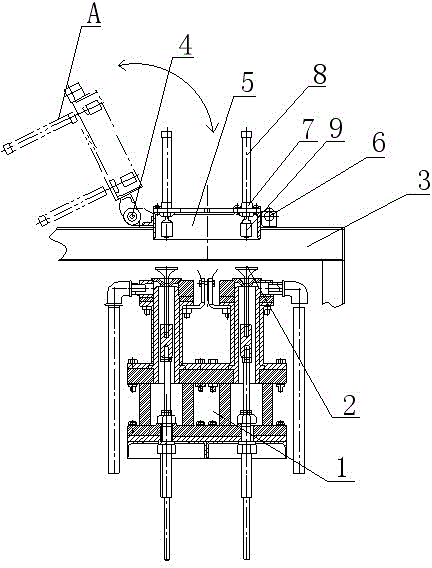
[0013] Such as figure 1 As shown, the process device for valve electroplating of the present invention comprises an electroplating device 1, two valves 2 are arranged on the electroplating device 1, and a fixed support 3 is arranged above the electroplating device 2, and the fixed support 3 is connected to the cathode movable support 5 through the flip hinge 4. Flexible connection, one side of the cathode movable support 5 is also provided with a locking pin 6 fixedly connected with the fixed support 3, a conductive clamping cylinder 7 is installed on the cathode movable support 5, and two piston rods 8 are installed on the conductive clamping cylinder 7 , the lower end of each piston rod 8 is equipped with a conductive head 9, and the position of the conductive head 9 is directly above the valve 2. During the electroplating process, the cathode movable support 5 is first turned over to the disassembly position A through the turning hinge 4, and then the valve 2 is put into th...


PUM


Abstract

The invention discloses a process device for electroplating air valves. The process device comprises an electroplating unit and is characterized in that a plurality of air valves are arranged on the electroplating unit, a fixing support is arranged above the electroplating unit and is movably connected with a cathode movable support through a turnover hinge, a locking pin which is fixedly connected with the fixing support is arranged on one side of the cathode movable support, a conductive clamping air cylinder is mounted on the cathode movable support, a plurality of piston rods are mounted on the conductive clamping air cylinder, conductive heads are arranged at the lower ends of the piston rods, and the positions of the conductive heads are above the air valves. The process device for electroplating air valves has the advantages that the conductive clamping air cylinder is not easy to damage, and the production efficiency is improved; the maintenance time is reduced, so that the device utilization rate and the device perfectness ratio are improved; as the conductive heads are turned upward, cleaning is facilitated, and effects on the production efficiency as the conduction of the conductive heads is poor are avoided; and the auxiliary time of electroplating armoring is decreased.

Description

technical field [0001] The invention relates to a process device for valve electroplating. Background technique [0002] The most widely used cathode electroplating method for valve plating is the spring clamping type, which mainly uses the pressure of the spring to clamp the cathode and the valve to conduct electricity. The main disadvantage of the spring clamping type is that it is inconvenient to assemble and disassemble. Poor contact, electric shock burns and intermittent power supply during the valve plating process; another cathode conductive device is a translational cylinder conductive device, but the main disadvantage of the translational cylinder conductive device is that the conductive device will clamp the cylinder during the translation process. The piston rod of the cylinder is bent due to the lack of retraction, which leads to the failure of the conductive clamping cylinder. At the same time, the cathode conductive connection position and the conductive head a...

Claims


Application Information

Patent Timeline
Patent Type & Authority Applications(China)
IPC IPC(8): C25D17/06
Inventor 仇士学卢杰初
Owner 鹰普航空科技(南通)有限公司
Why Eureka
Try Eureka