
Dynamic point-the-bit rotary steering drilling tool

A technology of rotary steerable drilling and dynamic pointing, applied in directional drilling, drilling equipment, automatic control system of drilling, etc., can solve the problems of inability to know the details of the eccentric mechanism, damage to the static state of the eccentric shaft, and small acting torque.

Inactive Publication Date: 2013-02-06
CHINA UNIV OF PETROLEUM (EAST CHINA)
View PDF8 Cites 36 Cited by
  • Summary
  • Abstract
  • Description
  • Claims
  • Application Information

AI Technical Summary

Problems solved by technology

[0005] Chinese patent announcement number CN 101586440A, published on November 25, 2009, the name of the invention is a pointing rotary steerable drilling tool (this invention application is also a utility model patent authorization, authorized announcement number: CN 201450731U, authorized announcement date May 12, 2010), the application discloses a pointing rotary steerable drilling tool system that does not depend on the surface mechanical properties of the formation, has a simple structure, and can accurately and effectively control the wellbore trajectory. The pointing type rotary steerable drilling tool system has the disadvantages that ① the outer cylinder does not rotate when the drilling tool is working, and its acting torque is small; ② the guiding of the drilling tool is realized by bending the mandrel, and the guiding mandrel needs to Under high-strength alternating stress, prone to fatigue damage
Its characteristic is that when the azimuth angle needs to be adjusted without adjusting the bending angle of the structure, the geographical static state of the eccentric shaft must be destroyed first, and when the eccentric shaft rotates to the required azimuth, it is then made to track the rotation speed of the outer cylinder at a constant speed in reverse, and at the same time The case failed to clarify the driving mode of the eccentric ring clearly and in detail, and the details of the eccentric mechanism could not be known

Method used


Image

  • Dynamic point-the-bit rotary steering drilling tool
  • Dynamic point-the-bit rotary steering drilling tool
  • Dynamic point-the-bit rotary steering drilling tool

Examples


Embodiment Construction

[0026]The technical solutions in the embodiments of the present invention will be further clearly and completely described below in conjunction with the drawings in the embodiments of the present invention. Obviously, the present invention is not limited by the following examples, and the specific implementation manner can be determined according to the technical solutions of the present invention and actual conditions. Based on the embodiments of the present invention, all other embodiments obtained by persons of ordinary skill in the art without making creative efforts shall fall within the protection scope of the present invention.

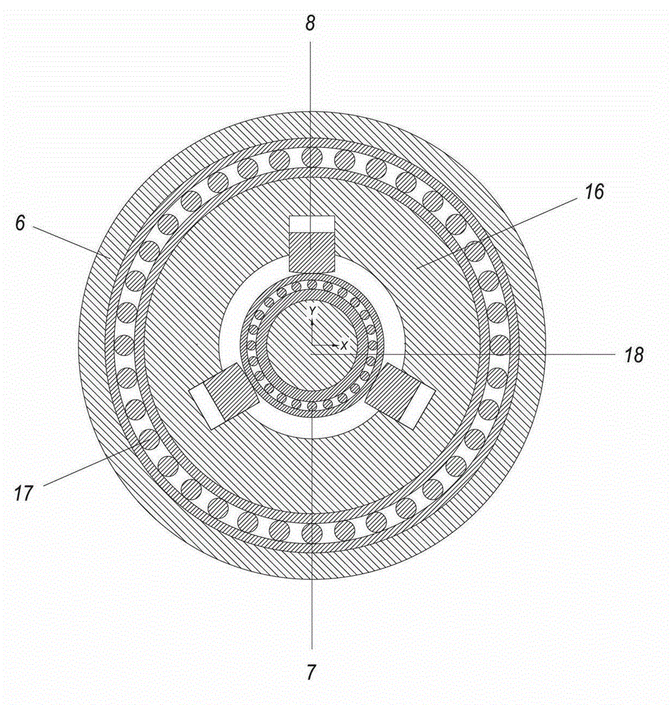
[0027] Embodiments of the present invention provide a downhole dynamic pointing rotary steerable drilling tool for but not limited to oil and gas development, in particular provide an offset steering mechanism based on a stable platform and a hydraulically driven piston. The guiding mode of the tool is pointing type, and the working mode of the...


PUM


Abstract

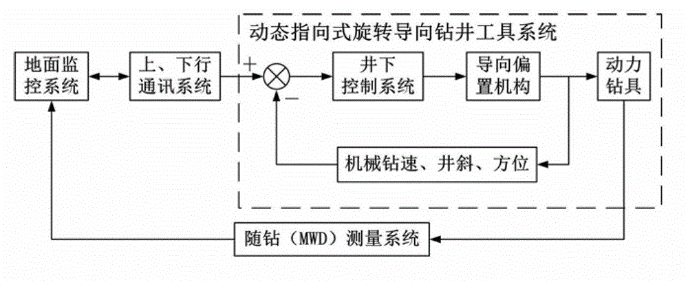
The invention relates to a dynamic point-the-bit rotary steering drilling tool. The dynamic point-the-bit rotary steering drilling tool comprises a rotary outer cylinder, a stable platform, a steering offset mechanism, a bit pressure transfer mechanism, a torque transfer mechanism, an upper support plate, a lower support plate, a drill shaft, a drill bit, a sealed corrugated pipe, a drill shaft connecting bearing and a conductive slip ring, and is characterized in that the rotary outer cylinder is used for directly applying bit pressure and torque on the drill bit and driving the drill shaft and the drill bit to rotate jointly, information of hole deviation angle and azimuth angle to be controlled can be calculated by a calculating unit according to a preset borehole trajectory parameter or a remote control command of a ground monitoring system, and precision control of bend angle, in particular to the hole deviation angle and the azimuth angle of the offset mechanism can be realized by adopting a geostationary control method of the stable platform and combining with working principles of a hydraulic drive piston and the steering offset mechanism.

Description

technical field [0001] The invention relates to the technical field of oil and gas drilling, in particular to a dynamic pointing rotary steerable drilling tool. Background technique [0002] As most oil and gas fields at home and abroad have successively entered the middle and late stages of development, the difficulty of oil and gas reservoir development has gradually increased, and the characteristics of the drilled formations have become increasingly complex. Drilling technologies such as multilateral wells put forward higher requirements. Rotary steerable drilling technology is a cutting-edge closed-loop automatic drilling technology developed in recent years, and its appearance is a qualitative leap in the world's drilling technology. [0003] The downhole rotary steerable drilling tool system is divided into push-and-point type and point-to-point type according to its guiding mode, and can be divided into static bias type and dynamic bias type according to the working...

Claims


Application Information

Patent Timeline
IPC IPC(8): E21B7/04E21B4/00E21B44/00
Inventor 鄢志丹耿艳峰杨锦舟吴仲华
Owner CHINA UNIV OF PETROLEUM (EAST CHINA)
Learn More