Bottom-adjustable propeller-type flying object

A technology of propeller type and flying body, which is applied in the direction of aircraft, unmanned aircraft, rotorcraft, etc., can solve the problems of reduced power efficiency, increased volume and weight, and low power efficiency, so as to reduce failure and damage, reduce Size and weight, structure and adjustments for simple effects

Inactive Publication Date: 2013-02-06
选择产业株式会社
View PDF5 Cites 7 Cited by
  • Summary
  • Abstract
  • Description
  • Claims
  • Application Information

AI Technical Summary

Problems solved by technology

[0003] As far as the existing lower wing-shaped flying body is concerned, the balance of the flying body is achieved by using sensors or stabilizer bars to adjust the pitch of the rotor every moment the flying body loses balance, or in order to stop, advance, retreat and Rotate left and right and set the adjustable wings in the lower part of the flying body in a manner that traverses the axis, or set the adjustable wings for forward and backward and the adjustable wings for left and right rotation separately on the lower part of the flying body. Its structure and adjustment device are complicated, and there is a problem of low power efficiency due to the change of rotor pitch angle
[0004] Moreover, the lower airfoil type airfoil, which uses a fixed-pitch propeller to provide an adjustable wing under the airfoil, has a complex structure composed of multiple elements such as a servo for adjusting the adjustable airfoil, an adjustment plate, and a hinge. , and the hinges used to install the adjustment plate and the adjustable wing are exposed, so they are easily damaged and inconvenient to manage, and the combination of multiple structural elements causes increased volume and weight, and there is a problem of reduced power efficiency caused by this

Method used


Image

  • Bottom-adjustable propeller-type flying object
  • Bottom-adjustable propeller-type flying object
  • Bottom-adjustable propeller-type flying object

Examples


Embodiment Construction

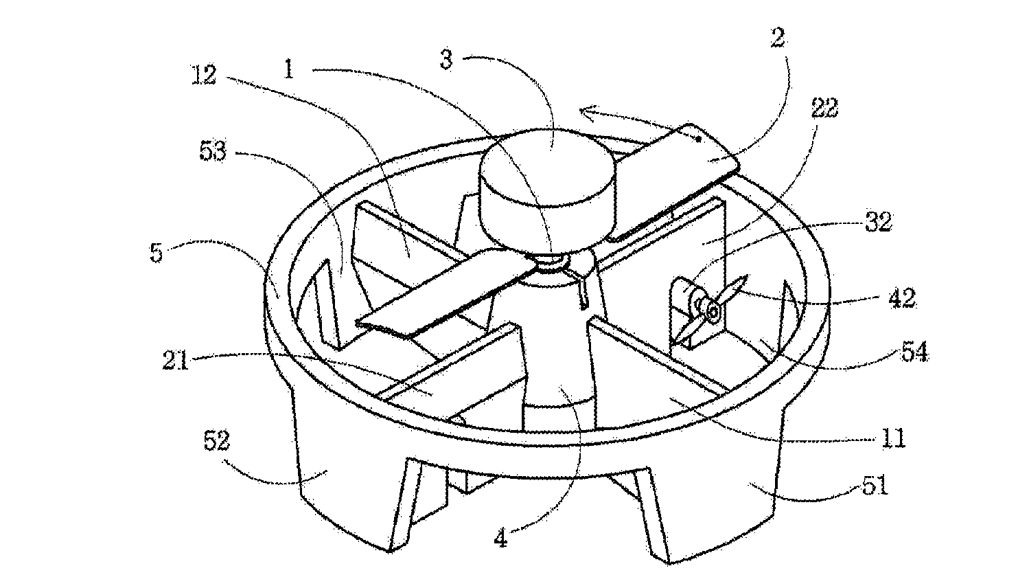
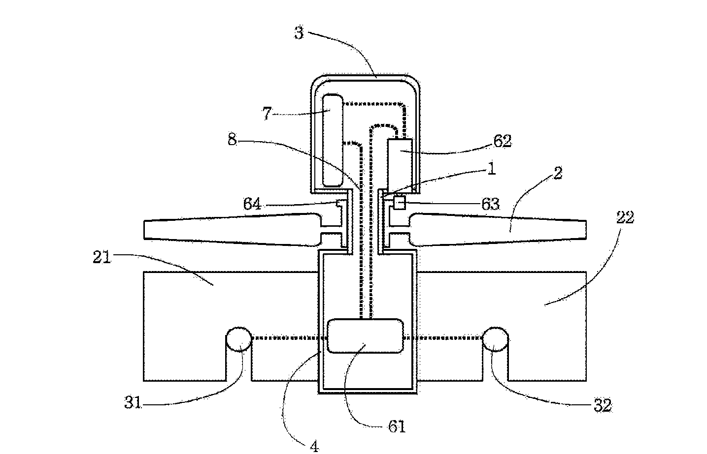
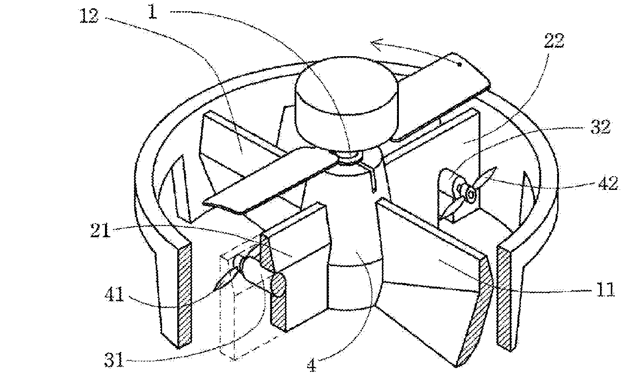
[0020] In order to achieve the above-mentioned purpose, with reference to the present invention as a perspective view figure 1 , remove figure 1 The circular frame 5 and foot plate 51,52,53,54 as figure 1 Conceptual longitudinal section view of figure 2 , and cut off figure 1 part of as a stereogram image 3 , illustrating the structure of the present invention as follows.

[0021] The lower adjustable propeller flying body of the present invention includes: a fixed-pitch power propeller 2 with a plurality of blades installed on the outer periphery of the central shaft 1 as the shaft in the shape of a hollow circular tube; it is arranged on the above-mentioned central shaft 1 top The power section 3; the control section 4 arranged at the bottom of the above-mentioned central shaft 1; the first and second fixed plates 11, 12 and the first and second protective plates 21, 22; the circular frame 5 and the foot plate 51 in the shape of a ring , 52, 53, 54; and the first and ...


PUM


Abstract

The present invention relates to a flying object having small bottom blades, which is one type of unmanned rotor craft. A conventional bottom blade type flying object needs an apparatus having a complex configuration constituted by the combination of various components, such as servo, control plate, hinge, and so forth to control the rotor pitch at every instant and operate a control blade for flight control. However, the present invention provides a bottom-adjustable propeller-type flying object, wherein a circular frame with a fixing plate and a protective plate mounted thereto is installed at a lower part of an axis of a power propeller mounted to the center axis, and a control motor having a control propeller installed thereto is mounted to the protective plate.; Accordingly, the flying object performs upward and downward flights using wind force generated by rotation of the power propeller, and performs hovering, and leftward, rightward, forward and rearward flights using wind force generated by rotation of the control propellers that are installed on two control motors. Further, components are arranged in such a manner as to locate a weight center of the flying object near the center axis.

Description

technical field [0001] The invention relates to a lower adjustable propeller flying body, in particular to a type of unmanned rotary wing aircraft as a small lower wing type flying body with an adjustable lower propeller. Background technique [0002] The lower airfoil type flying body generally includes a rotor or propeller that rotates with power around the central axis of the flying body, a power part, a control part, a fixed plate, an adjustable wing, etc., and is installed on the bottom of the propeller. A flying object that performs flight by the action of adjustable wings. [0003] As far as the existing lower wing-shaped flying objects are concerned, sensors or stabilizer bars are used to adjust the pitch of the rotor to achieve the balance of the flying objects at every moment when the flying objects are out of balance, or in order to stop, advance, retreat and stop the flying objects. Rotate left and right and set the adjustable wing in the lower part of the flyin...

Claims


Application Information

Patent Timeline
Patent Type & Authority Applications(China)
IPC IPC(8): B64C27/20A63H27/127B64C29/00B64C39/02
CPCB64C2201/165A63H27/12B64C27/82B64C2201/027B64C2201/108B64C39/024B64C27/20B64U10/13B64U50/20B64U30/29B64U60/50B64U30/20B64U50/13
Inventor 催基东催基南
Owner 选择产业株式会社
Why Eureka
Try Eureka