Long cylinder barrel inner cavity cleaning machine
A cleaning machine and inner cavity technology, applied in the direction of cleaning hollow objects, cleaning methods and utensils, chemical instruments and methods, etc., can solve problems such as fire hazards, labor-intensive labor, and difficulty in cleaning, and reduce unsafe factors. , The effect of reducing labor intensity of workers and improving cleaning efficiency
- Summary
- Abstract
- Description
- Claims
- Application Information
AI Technical Summary
Problems solved by technology
Method used
Image

Examples
Embodiment 1
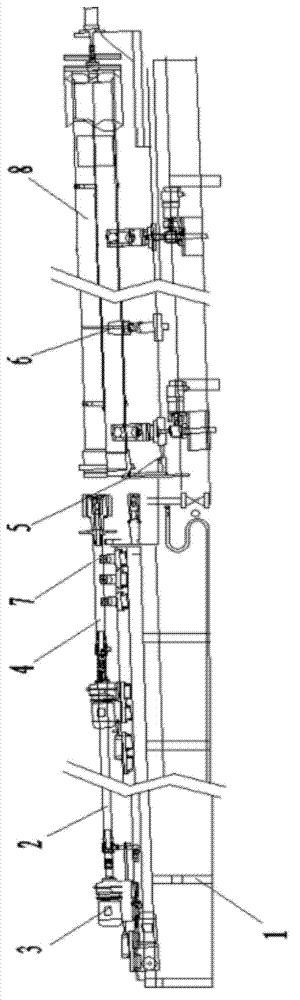
[0028] Such as figure 1 As shown, a long cylinder inner cavity cleaning machine includes a frame 1, a probe 2, a probe conveying device 3, a probe rotating device 4, a lifting positioning device 5, a pressing device 6, and a roller device 7. The probe 2 is fixed on the front end of the frame 1, the end of the probe 2 is fixed with a probe delivery device 3, the middle end of the probe 2 is fixed with an idler device 7, and the end of the probe 2 is fixed with a probe rotation device 4; The lifting and positioning device 5 is fixed on the rear section of the frame 1; the pressing device 6 is fixed on the table top of the rear section of the frame 1; the material of the probe 2 is a high-precision seamless steel pipe plated with hard chrome.
[0029] When performing operations, the cylinder 64 is fixed on the rear end table of the frame 1 through the pressing device 6, the probe delivery device 3 is opened, and the rear end of the probe 2 is fixed by the idler device 7 to preven...
Embodiment 2
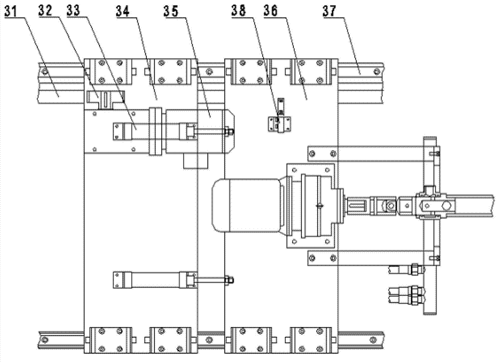
[0031] Such as figure 2 As shown, the probe conveying device 3 includes a rack 31, a gear 32, a cylinder 33, a carriage, a conveying reducer 35, a guide rail 37 and an electronic proximity switch 38, and the guide rail 37 includes two parallel guide rails. A rack 32 is fixed; the carriage includes an active carriage 34 and a passive carriage 36, and is placed on the guide rail 37 front and rear; the gear 32 is nested on the rack 31; the active carriage 34 and the passive carriage The plates 36 are connected by cylinders 33; the conveying reducer 35 is fixed on the active carriage 34; the electronic proximity switch 38 is fixed on the passive carriage 36; the number of the cylinders 33 is two; the active A gear 32 is fixed on the bottom surface of the carriage 34; the conveying reducer 35 is fixed on the active carriage 34 and drives the gear 32 on the bottom surface of the active carriage 34.
[0032] When working, push and pull the passive carriage 36 under normal circumsta...
Embodiment 3
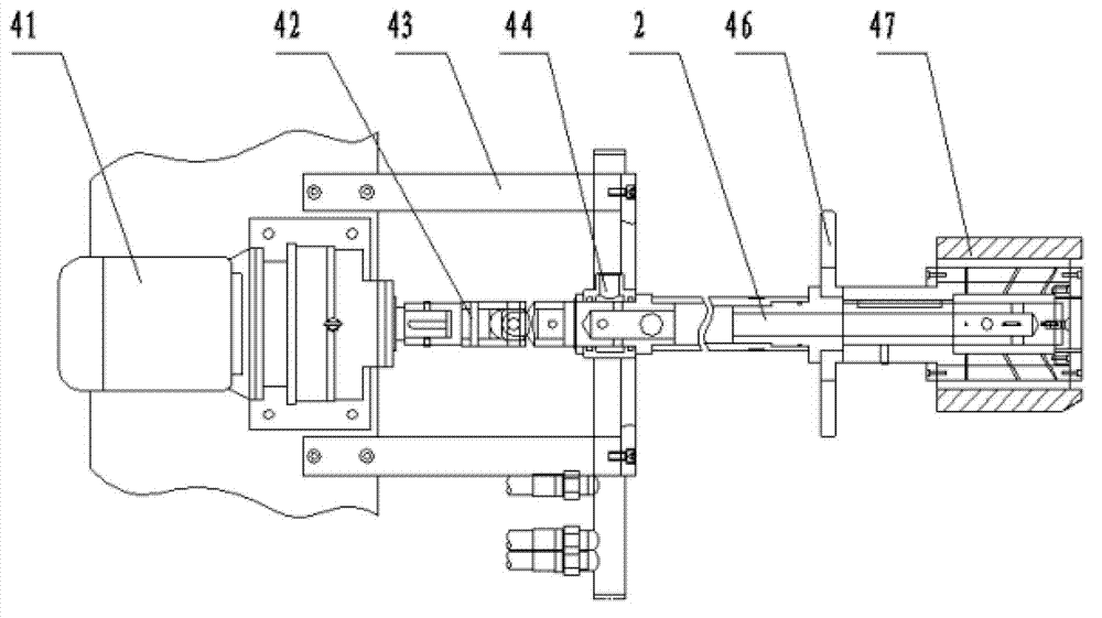
[0034] Such as image 3As shown, the probe rotation device 4 includes a rotation reducer 41, a coupling 42, a frame 43, a valve sleeve 44, a probe 2, a guide piece 46 and a brush 47, and the rotation reducer 41 is fixed on the frame 43 Above, the output end of the rotary reducer 41 is fixed with the top of the coupling 42; the valve sleeve 44 is fixed at the end of the coupling 42; the top of the probe 2 is nested in the coupling 42, and the top of the probe 2 The end is fixed with a hair brush 47; the guide plate 46 is fixed at the connection between the probe 2 and the hair brush 47; the rotation reducer 41 is fixed on the frame 43 by fastening screws; the top of the probe 2 is embedded It is set in the coupling 42 and fixed by screws; the material of the probe 2 is a high-precision seamless steel pipe plated with hard chrome.
[0035] When working, the rotary reducer 41 drives the probe 2 to rotate, and the brush 47 nozzle installed at the end of the probe 2 scrubs the inn...
PUM
| Property | Measurement | Unit |
|---|---|---|
| Length | aaaaa | aaaaa |
Abstract
Description
Claims
Application Information
 - Generate Ideas
- Intellectual Property
- Life Sciences
- Materials
- Tech Scout
- Unparalleled Data Quality
- Higher Quality Content
- 60% Fewer Hallucinations
Browse by: Latest US Patents, China's latest patents, Technical Efficacy Thesaurus, Application Domain, Technology Topic, Popular Technical Reports.
© 2025 PatSnap. All rights reserved.Legal|Privacy policy|Modern Slavery Act Transparency Statement|Sitemap|About US| Contact US: help@patsnap.com