Micropump being easy to assemble

A micro-pump and exhaust valve technology, which is used in pump components, variable-capacity pump components, liquid variable-capacity machinery, etc., can solve the problem that the exhaust valve is not installed properly, the construction period is delayed, and the exhaust valve is missing. and other problems, to achieve good promotion potential, reduce working noise, and improve the speed of assembly.

Active Publication Date: 2013-02-13
XIAMEN KOGE MICRO TECH
View PDF6 Cites 6 Cited by
  • Summary
  • Abstract
  • Description
  • Claims
  • Application Information

AI Technical Summary

Problems solved by technology

[0004] However, during the assembly process, if the workers install three exhaust valves manually, one of the exhaust valves may not be installed in place, or even one of the exh...

Method used


Image

  • Micropump being easy to assemble
  • Micropump being easy to assemble
  • Micropump being easy to assemble

Examples


Embodiment 1

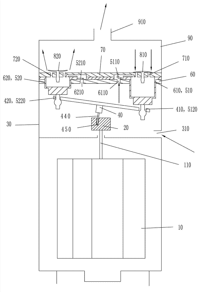
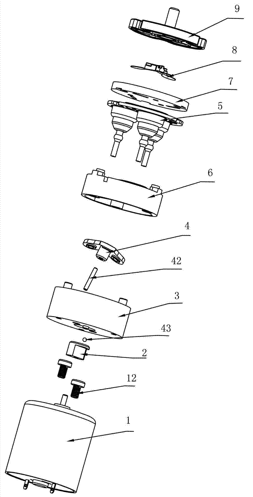
[0048] For the unfolded structure of an embodiment of the micropump that is easy to assemble of the present invention, please refer to figure 2 . The easy-to-assemble micropump has a motor 1, an eccentric wheel 2, a base 3, a steel needle 44, a ball 45, an umbrella-shaped connecting rod 4, a piston body 5, a cylinder plate 6, an air chamber pressure plate 7, an exhaust valve plate group 8 and upper cover9.

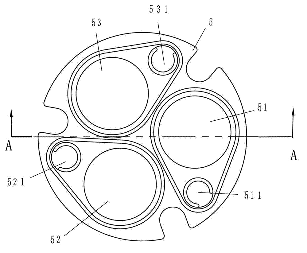
[0049] Please see image 3 with Figure 4 : Piston body 5 made of rubber, three hollow pistons 51, 52, 53 extending downward and three intake valve plates 511, 521, 531 evenly distributed on the flat plate portion of its upper end, three pistons 51, 52 The lower ends of , 53 are respectively provided with engaging portions 512 , 522 , 532 extending downward.

[0050] Please see Figure 5 with Image 6 The three pistons 51, 52, 53 corresponding to the piston body 5 on the cylinder plate 6 are provided with three corresponding cylinder holes 61, 62, 63. The upper sur...

Embodiment 2

[0060] Another embodiment of the micropump that is easy to assemble of the present invention has motor 1, eccentric wheel 2, base 3, steel needle 44, ball 45, umbrella-shaped connecting rod 4, piston body 5 and cylinder plate 6 as previous embodiment, for Their structures and connections will not be described in detail. But the structure and connection relationship of the air chamber pressing plate 7', the exhaust valve sheet group 8' and the loam cake 9' in the present embodiment are different from the previous embodiment.

[0061] Please see Figure 16 Three pistons 51, 52, 53 corresponding to the piston body 5 on the air chamber pressing plate 7 ' are provided with three corresponding exhaust holes 71 ', 72 ', 73 '. In the middle of the upper end surface of the air chamber pressure plate 7', corresponding to the three exhaust holes 71', 72', 73', a triangular central groove 701' is arranged. The air holes 71', 72', 73' are respectively provided with circular grooves 705',...

Embodiment 3

[0069]Another embodiment of the micropump that is easy to assemble of the present invention has motor 1, eccentric wheel 2, base 3, steel needle 44, ball 45, umbrella-shaped connecting rod 4, piston body 5 and cylinder plate 6 as first embodiment, Their structures and connection relationships will not be described in detail. However, the structure and connection relationship of the air chamber pressing plate 7 ″, the exhaust valve sheet group 8 ″ and the upper cover 9 ″ in this embodiment are different from those in the first embodiment.

[0070] Please see Figure 20 : Three pistons 51, 52, 53 corresponding to the piston body 5 on the air chamber pressure plate 7" are provided with three corresponding exhaust holes 71", 72", 73". Corresponding to the three exhaust holes 71", 72", and 73" in the middle of the upper end surface of the air chamber pressure plate 7, a triangular central groove 701" with a side line concave inward is provided, and on the three vertices of the cen...


PUM


Abstract

The invention relates to a micropump being easy to assemble, and relates to equipment of motor driven and transferring gas. The micropump is provided with a motor, a cylindrical base, an eccentric wheel with an oblique cutting hole, a steel needle, an umbrella type connecting rod with three clamping holes, an air cylinder plate with three air cylinder holes, a piston body with three air inlet valve pieces and three hollow pistons, an air chamber press plate with three exhaust holes, an upper cover with an exhaust pipe and three air outlet valve pieces, wherein a connecting part can enable the three air outlet valve piece to connect with a row of air outlet valve piece groups; the connecting part is provided with a triangular plain film or three starlight pattern bulges, and three top angles of the connecting part are respectively connected with one air outlet valve piece; and the air outlet valve piece groups are arranged in the inner space between the upper cover and the air chamber press plate, and three air outlet valve pieces in the air outlet valve piece groups respectively cover corresponding exhaust holes on the air chamber press plate. The micropump can avoid the phenomenon that one air outlet valve piece is not installed on a place in an assembling process, and even the phenomenon that one air outlet valve piece is leaked.

Description

technical field [0001] The invention relates to a device driven by a motor for conveying gas. Background technique [0002] The existing micropump driven by a motor and transporting gas, its main structure and working principle are as follows: figure 1 As shown: the motor 10 is installed at the lower end of a cylindrical base 30 , and an air inlet 310 is opened on the side wall of the base 30 . An eccentric wheel 20 and an umbrella-shaped connecting rod 40 are arranged in the base 30 . The eccentric 20 is mounted on the main shaft 110 of the motor 10 . The upper part of the eccentric wheel 20 is provided with an inwardly inclined oblique insertion hole, and a steel needle 440 and a ball 450 are arranged in the oblique insertion hole. The lower surface of the steel needle 440 bears against the ball 450 at the bottom of the oblique insertion hole, and the upper end of the steel needle 440 stretches out of the oblique insertion hole and is fixedly connected to the main shaft...

Claims


Application Information

Patent Timeline
IPC IPC(8): F04B39/10
Inventor 张坤林
Owner XIAMEN KOGE MICRO TECH
Why Eureka
Try Eureka