Circumferential groove casing treatment method

A casing processing and circumferential groove technology, applied in mechanical equipment, machines/engines, liquid fuel engines, etc., can solve the problems of efficiency reduction, expansion of compressor stable working margin, etc., to achieve convenient processing, high social benefits and Promote the value and improve the effect of compressor performance

Active Publication Date: 2013-02-13
XI AN JIAOTONG UNIV
View PDF4 Cites 9 Cited by
  • Summary
  • Abstract
  • Description
  • Claims
  • Application Information

AI Technical Summary

Problems solved by technology

A widely used form of casing treatment is circumferential groove casing treatment. The traditional circumferential groove casing treatment is often carried out on the compressor rotor, but it often causes a decrease in efficiency while expanding the stable working margin of the compressor.

Method used


Image

  • Circumferential groove casing treatment method
  • Circumferential groove casing treatment method
  • Circumferential groove casing treatment method

Examples


Embodiment Construction

[0022] The present invention will be described in further detail below in conjunction with the accompanying drawings.

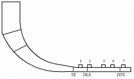
[0023] 1) First, model the compressor without slots on the side of the wheel cover, and conduct numerical simulation and flow analysis of its internal flow field to determine the dominant flow field structure and flow characteristics in the compressor, and clarify the compressor flow Areas within the track prone to stalling;

[0024] 2) Secondly, according to the area in the compressor flow channel determined in step 1) that is prone to stall, a single circumferential groove is opened along the different meridian positions of the compressor shroud side, and modeling and numerical simulation are performed on it, and the circumferential groove machines at different positions are compared Determine the best slotting position based on the expansion stability effect of the box and its influence on the efficiency of the compressor;

[0025] 3) Then, according to t...


PUM


Abstract

The invention provides a circumferential groove casing treatment method of a centrifugal compressor. The circumferential groove casing treatment method completely takes structure characteristics and internal flow situations of the centrifugal compressor into consideration. A groove is arranged in a position prone to speed reduction of a diffuser channel along the circumference of a wheel cap side so as to provide a backflow channel for low-speed fluid in a top area of the diffuser, and then lower-power fluid lump is pumped into a treatment groove and transported along the circumference direction and flow direction of the treatment groove. In the process, only part of the fluid refills into a main fluid, the area of lower-power fluid is reduced and flow speed is improved, flow situations of the top channel of the diffuser are improved, blocking of the top channel is weakened, steady operation range of the compressor is enlarged greatly, and meanwhile peak value efficiency and pressure ratios are improved.

Description

technical field [0001] The invention relates to a treatment method for a casing of a centrifugal compressor, in particular to a treatment method for a circumferential groove casing. Background technique [0002] Centrifugal compressors have the advantages of small size, high single-stage pressure ratio and simple structure, and are increasingly used in many fields. In recent years, with the continuous improvement of people's demand and interest in micro-energy conversion systems, high speed, high pressure ratio, high efficiency, wide working conditions, and miniaturization have become one of the important trends in the development of centrifugal compressors, and their Performance makes increasingly demanding demands. Today's development trend of high speed and high load of compressors poses new challenges to the stable operation of compressors and its stability expansion technology, especially the unsteady flow instability represented by rotating stall and surge is a threat...

Claims


Application Information

Patent Timeline
Patent Type & Authority Applications(China)
IPC IPC(8): F04D29/42
Inventor 席光马岩
Owner XI AN JIAOTONG UNIV
Why Eureka
Try Eureka