Signal collecting circuit
A signal acquisition and circuit technology, applied in the direction of using electric devices, electromagnetic means, and thermometers using electric/magnetic elements that are directly sensitive to heat, can solve the problem of affecting the performance and service life of motors and controllers, and the temperature of the measured point Inaccuracies, deviations, etc.
- Summary
- Abstract
- Description
- Claims
- Application Information
AI Technical Summary
Problems solved by technology
Method used
Image
Examples
Embodiment 1
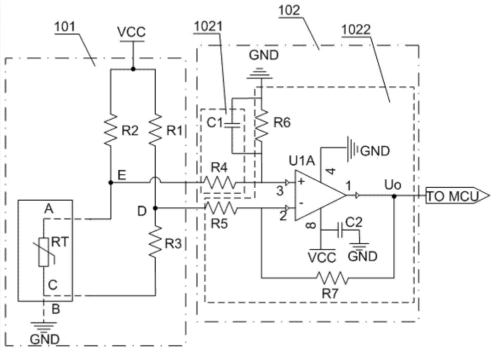
[0042] The present application provides a signal acquisition circuit, including: a power supply VCC, a bridge circuit 101 and a voltage measurement circuit 102;
[0043] Wherein, the power supply VCC provides voltage for the signal acquisition circuit;
[0044] The bridge circuit 101 is connected to the power supply VCC for receiving the voltage provided by the power supply VCC, and a temperature sensor is arranged in a bridge arm of the bridge circuit;
[0045] The voltage measurement circuit 102 is used to measure the voltage value of the temperature sensor from the bridge circuit 101, and send the voltage value to the main control chip MCU to calculate the temperature value measured by the temperature sensor.
[0046] see figure 2 It shows a schematic diagram of a signal acquisition circuit provided in Embodiment 1 of the present application, including: a power supply VCC, a bridge circuit 101 and a voltage measurement circuit 102;
[0047] Such as figure 2 As shown, i...
Embodiment 2
[0098] see Figure 5 , showing a schematic diagram of Embodiment 2 of a signal acquisition circuit provided by the present application, in Figure 4 The circuit shown also includes: a voltage stabilizing circuit 103;
[0099] The voltage stabilizing circuit 103 is used to stabilize the voltage value output from the power supply VCC to the bridge circuit 101 at a reference voltage value.
[0100] Unstable voltage will affect the measurement and calculation of the subsequent voltage value, so the voltage stabilization circuit 103 is used to stabilize the voltage value output by the power supply VCC at the reference voltage value.
[0101] The voltage stabilizing circuit 103 includes: a power chip U2 and a variable resistor R8;
[0102] Wherein, the power chip U2 is connected in series with the voltage dividing resistor R0, and the anode 3 of the power chip U2 is connected to the junction of the voltage dividing resistor R0, the first resistor R1 and the third resistor R3, and ...
PUM
 Abstract
Description
Claims
Application Information
 - R&D
- Intellectual Property
- Life Sciences
- Materials
- Tech Scout
- Unparalleled Data Quality
- Higher Quality Content
- 60% Fewer Hallucinations
Browse by: Latest US Patents, China's latest patents, Technical Efficacy Thesaurus, Application Domain, Technology Topic, Popular Technical Reports.
© 2025 PatSnap. All rights reserved.Legal|Privacy policy|Modern Slavery Act Transparency Statement|Sitemap|About US| Contact US: help@patsnap.com


